background image

ENGLISH

9

A fused disconnect switch or a main circuit breaker 
(customer furnished) MUST be installed in the 
electric supply line for the appliance. It is recom-
mended that this switch/circuit breaker have 
lockout/tagout capability. Before making any electri-
cal connections to this appliance, check that the 
power supply is adequate for the voltage, amperage, 
and phase requirements on the rating plate.

RATING PLATE

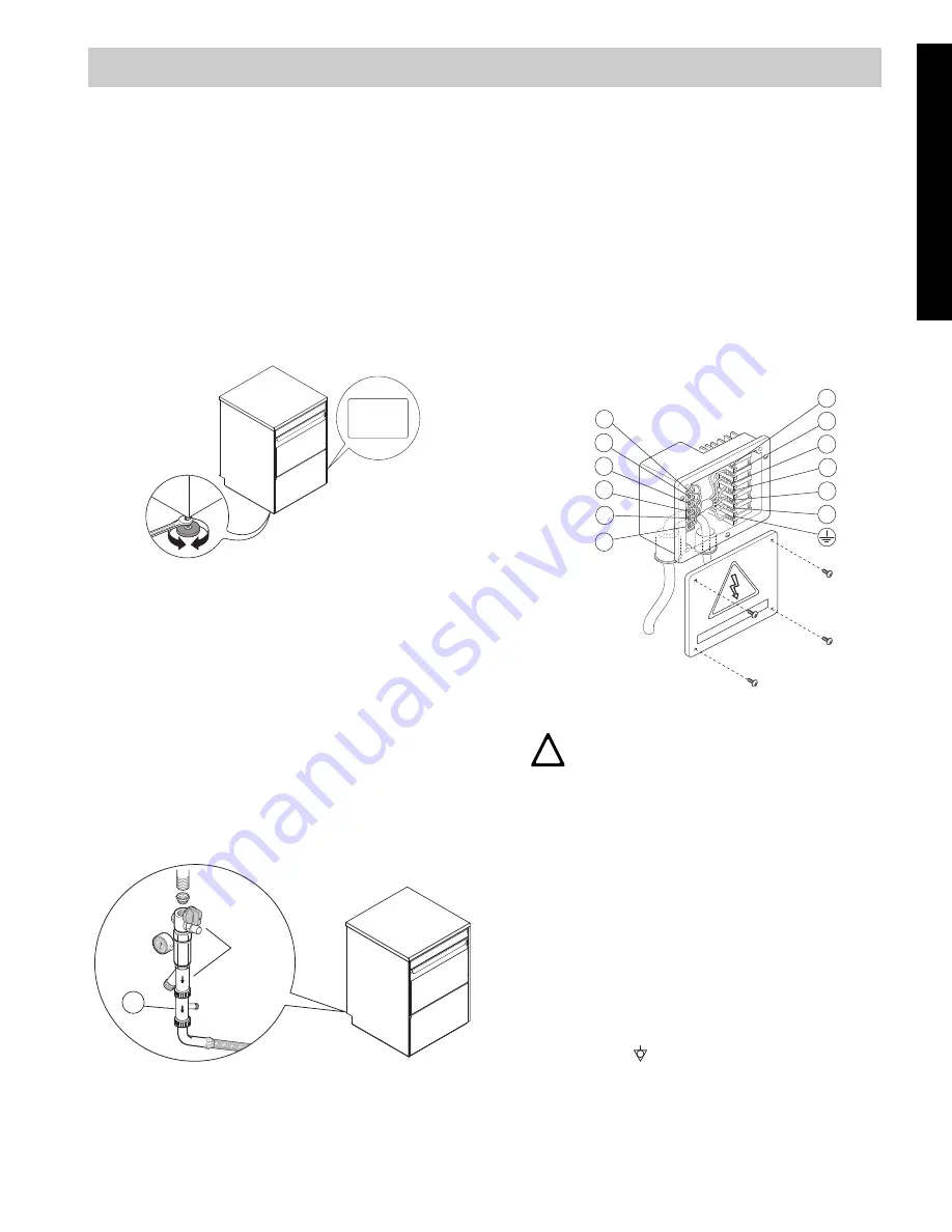
The rating plate contains identification and technical 
data and is located on the right-hand side panel of the 
appliance (Figure 5).

Figure 5

C1

WATER CONNECTION

• Position the dishwasher and level the appliance by 

adjusting the appropriate bullet feet (Figure 5).

• Connect the appliance water supply pipe “A” 

(Figure 4) (keeping with local plumbing codes) to the 
incoming water supply. Install a shutoff valve, Y-
Strainer, and a pressure gauge between the appli-
ance and the incoming water supply of the unit 
(Figure 6).

• In models with incorporated water softener, connect 

the double non-return valve "B" (Figure 6) supplied 
and the machine supply pipe.

Figure 6

Check that the 

dynamic

 water supply 

pressure

 measures 

between 

7.25 - 101 psi/50 - 700kP

while dishwasher 

tank or boiler is filling with water. 

If the pressure is too high, install a suitable pressure 
regulator on the incoming water supply to the unit.

Position the outlet pipe at a height anywhere between 29 
1/2” to 39 3/8”/750 to 1000mm from the floor.
Check that about 1 gallon/4 litres of water flow out of the 
outlet pipe during the rinse cycle.

Make sure drain hose does not kink, pinch or twist, 
resulting in a water flow restriction.

C2

ELECTRICAL CONNECTION

Figure 7

The installation of this unit must conform to local 
codes or, in the absence of local codes, to all Natio-
nal Codes governing plumbing, sanitation, safety 
and good trade practices.

• Check the over rating plate before making any 

electric supply connections. Electric supply connec-
tions must agree with data on the unit rating plate.

• The earth wire at the terminal end must be 

3/4”/20mm (max.) longer than the phase wires.

• The appliance requires a ground connection to the 

unit ground screw located at the rear of the unit 
marked “Q” (Figure 4) in the manual and marked with 
the symbol “ “ on the unit. The ground wire must 
have a cross section of AWG 8/8.35 mm

2

. Do not use 

the wiring conduit or other piping for ground connec-
tions. If necessary, have the electrician supply the 
ground wire.

C

INSTALLATION AND START-UP INSTRUCTIONS

Model LS6 
PNC 9CGX 502003  05   Ser.N .123000001
AC 400V 3N                50Hz
Power Boiler              16500w
Power Tank                 7500w
Power Max                26800w
       Made in EEC
Model RT10 ED
PNC    9CGX502003 05
Ser.N .123000001

!

B

CAUTION


THE ELECTRICAL CONNECTIONS 
MUST MEET ALL NATIONAL AND 
ELECTRICAL CODE REQUIREMENTS.

AC  400....

1

11

10

9

8

7

6

5

4

3

2

12

!

Summary of Contents for Energy Star WT30H208DU

Page 1: ... C2 ELECTRICAL CONNECTION Pag 9 C3 WARNING MESSAGES DISPLAYED ON THE CONTROL PANEL Pag 10 C4 DETERGENT RINSE AID DISPENSERS AND SETTINGS Pag 11 C5 SETTING THE DISPENSERS Pag 12 D USER INSTRUCTIONS Pag 14 D1 STARTING Pag 14 D2 WASH CYCLES Pag 15 D3 OPERATION Pag 15 D4 END OF WORK AND DAILY CLEANING Pag 16 D5 MAINTENANCE Pag 17 D6 UNDERCOUNTER DISHWASHER WITH INCORPORATED CONTINUOUS WATER SOFTENER P...

Page 2: ...not touch the heating element during or immediately after use The installation of this unit must conform to local codes or in the absence of local codes to all National Codes gover ning plumbing sanitation safety and good trade practices BEFORE SERVICING DISCONNECT THE ELECTRICAL SERVICE AND PLACE A RED TAG AT THE DISCON NECT SWITCH TO INDICATE WORK IS BEING DONE ON THAT CIRCUIT NOTICE CONTACT YOU...

Page 3: ...be sure to ask for OEM original spare parts NOTICE FOR SHIPPING DAMAGE The container should be examined for damage before and during unloading The freight carrier has assumed responsibility for its safe transit and delivery If damaged equipment is received either apparent or concealed a claim must be made with the delivering carrier Apparent damage or loss must be noted on the freight bill at the ...

Page 4: ...llows Wood and cardboard components may be disposed of according to local regulations in force Appliances that have reached the end of their service life should be sui tably disposed of The appliance should be dismantled according to regulations in force All metal parts are in stainless steel AISI 304 and are removable Plastic parts are marked with the symbol of the material polyethylene external ...

Page 5: ...40 ppm 14 fH max Water supply hardness for models with incorporated continuous water softner 400 ppm 40 fH max 400 ppm 40 fH max Rinse cycle water consumption 0 90 gallons 3 4 liters 0 90 gallons 3 4 liters Boiler capacity 3 gallons 12 liters 3 gallons 12 liters Tank capacity 6 gallons 23 liters 6 gallons 23 liters Standard cycle time with water supply at 122 F 50 C 120 180 240 seconds 120 180 240...

Page 6: ... 5 8 23 5 8 600 mm 600 mm 20 20 508 mm 508 mm 2 2 50 mm 50 mm A A C C I I S S Y Y 38 3 8 38 3 8 975 mm 975 mm 2 3 4 2 3 4 70 mm 70 mm 17 17 431 mm 431 mm 1 3 4 1 3 4 44 mm 44 mm 29 1 2 29 1 2 750 mm 750 mm 39 3 8 39 3 8 1000 mm 1000 mm A A I I I I S S Y Y Q Q 1 1 2 1 1 2 40 mm 40 mm Q Q Y Y I I C C A A S S 24 24 612 mm 612 mm 6 1 4 6 1 4 157 mm 157 mm 1 1 4 1 1 4 32 mm 32 mm 17 17 431 mm 431 mm 14...

Page 7: ...incoming water supply to the unit Position the outlet pipe at a height anywhere between 29 1 2 to 39 3 8 750 to 1000mm from the floor Check that about 1 gallon 4 litres of water flow out of the outlet pipe during the rinse cycle Make sure drain hose does not kink pinch or twist resulting in a water flow restriction C2 ELECTRICAL CONNECTION Figure 7 The installation of this unit must conform to loc...

Page 8: ... case of malfunctioning In the event of water mains failure a back flow device prevents water in the boiler from returning into the mains An overflow pipe connected to the drainage outlet maintains the water in the tank at a constant level On models with a drain pump a supplementary level control device activates if the main level control device is faulty Failure to comply with safety rules and re...

Page 9: ...xt paragraph Insert the hose provided in the kit into the detergent con tainer 2 Dishwashers with incorporated peristaltic rinse aid dispenser pump Figure 11 Pump S dispenses about 0 0046 oz per second 0 13 g per second of rinse aid It dispenses 0 014 oz 0 39 g in 3 sec at each rinse Dispenser operating time may be changed following the instructions given in the next paragraph Insert the hose prov...

Page 10: ...eration several times C5 SETTING THE DISPENSERS All operations should be carried out with the appliance switched on the door open and no cycle selected SEQUENTIAL START Press the indicated buttons simultaneously for 5 seconds Display of programming mode Initial amount of detergent Setting the activation time Initial amount of rinse aid Setting the activation time Amount of detergent during the cyc...

Page 11: ...r has been connected with a tank concentration measuring sensor a standard setting could be as follows dIn 0 the dispenser is not activated during filling of the tank dEt 181 the dispenser is activated during wash pump operation and thanks to the concentration mea sured by the conduction sensor the correct amount of detergent is dispensed Suggestion to check the effectiveness of the rinse aid look...

Page 12: ...ere is no automatic dispenser pour a non foaming detergent into the tank when the water has reached the washing temperature CONTROL PANEL Figure 14 The temperature shown on the display is that of the boiler if the indicator light E is on or of the tank if the light D is on The tank temperature is displayed during the wash cycle and the boiler temperature during the rinse cycle D1 STARTING Open the...

Page 13: ...n models without automatic dispenser Insert the rack containing the dirty dishes Close the door and select the suitable wash cycle the corresponding indicator light comes on and the wash cycle starts Cycle I For lightly soiled dishes or glasses press J button Figure 14 see table of times Cycle II recommended For normally dirty dishes press H button Figure 14 see table of times Cycle III For very d...

Page 14: ... not use sharp implements to clean the nozzle holes which could otherwise be damaged Remove filters C and D and clean them under a water spray Remove the filter Z and clean away any stuck on food in order to avoid blocking the draining system Figure 19 Upon completion of cleaning operations replace the parts removed previously Cleaning the exterior surfaces Before carrying out any cleaning operati...

Page 15: ... water Press on off A button Figure 14 The indicator light of the on off button A comes on indi cating the dishwasher is powered and the water is being introduced and heated The word FILL scrolls across display during the entire filling and heating stage The filling and heating stage has finished when the display shows the tank temperature Step 3 Pour the deliming agent Open the door pour the requ...

Page 16: ...ishwasher water circuit By means of special resins this device removes the calcareous substances from the feed water supplying decalcified water for washing For the continuous softener to work properly the resins must be regenerated periodically with frequency depen ding on the hardness of the water and the number of wash cycles carried out Unlike conventional water softeners this continuous sof t...

Page 17: ...ays has water in it therefore it is normal if water comes out during filling IMPORTANT only salt may be placed in the salt con tainer Do not introduce any other chemi cal substances such as detergent rinse aid or descaling agent since these would inevitably damage the appliance Such damage invalidates any warranty and relieves the manufacturer of all liability IMPORTANT The message SAL 0 may appea...

Page 18: ...d 194 F 90 C CONDENSATION ON GLASSES 1 Check that there is rinse aid in the container and if necessary top off level 2 Check the set amount of rinse aid see setting the dispensers para graph 3 Remove the rack of glasses immediately the cycle has ended STAINS ON THE GLASSES 1 Only use non foaming products for professional dishwashers EXCESSIVE FOAM IN THE TANK 1 Check that the wash water temperatur...

Reviews: