56
Installation manual
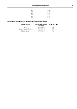
Table 4 (B2, C and correction factors for cable grouping)
B2
E
E
Number of cables
Seated in Cable Duct
Wall fixing or Cable trough
Cable tray
1
1.00
1.00
1.00
2
0.80
0.85
0.87
4
0.65
0.75
0.78
6
0.57
0.72
0.75
9
0.50
0.70
0.73
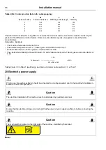
The total current included for using Table 1 should be the maximum rated current for the machine divided by the
product of the different correction factors. Other correction factors may also be applied ; consult the cable
manufacturers.
Calculation : Example
• The machine has a rated current of 60 A.
• The ambient temperature is 45 °C ; Table 2 gives a correction factor of 0.91.
• Rubber cable insulant : Table 3 gives a correction factor of 0.92.
• The cable is fixed directly to the wall (Column C), with 2 cables side by side. Table 4 gives a correction factor of
0.85.
60 A
Total current :
_________________
= 84 A
0.91 x 0.92 x 0.85
Taking Column C in Table 1 (wall fixing), we obtain a minimum cable section of : 3 x 25 mm².
20 Electricity power supply
Prior to use, the washer-extractor should be connected to a multi-pole switch prior to the machine to facilitate in-
stallation and service operations.
Caution
The electrical installation of the machine must be undertaken by qualified personnel.
Caution
Ensure that the electrical voltage is correct and that the power of your supply is sufficient, before connecting the
machine.
Caution
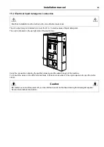
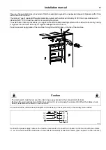
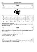
The main switch is located on the right side of the machine , identified by this sticker.
Note!
Summary of Contents for WP4 1100H
Page 2: ......
Page 4: ......
Page 25: ...Installation manual 25 6 3 Washer extractor type 900 One door WP4 900H Drawing 07100138 ...
Page 31: ...Installation manual 31 6 5 Washer extractor type 1100 One door WP4 1100H Drawing 07100136 ...
Page 53: ...Installation manual 53 ...
Page 66: ......
Page 67: ......
Page 68: ...Electrolux Professional AB 341 80 Ljungby Sweden www electroluxprofessional com ...

