42
Installation manual
Caution
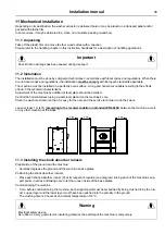
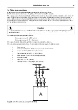
Only for machines with weighing equipment.
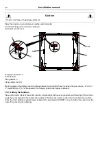
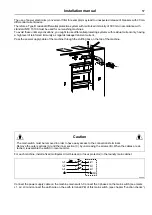
Place the machine on a perfectly even surface and horizontal.
Control this using a water level (see drawing).
Each point must be level.
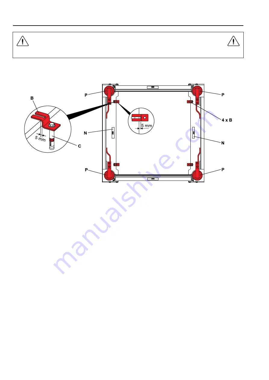
Weighing equipment: P
Water level: N
Fixing dowels: C
Flange safety locks: B
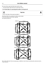
Mark the place of the drilling hole for the fixing dowels (C) and drill the holes for fixing of flanges (holes
⌀
12 mm (1/
2″), depth 80 mm (3″)). Put the dowels in the flanges, position the flanges and screw.
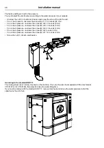
11.5 Setting the bolsters
Place each bolster (G) at its respective location (see drawing) and heave successively each bearing of the machine.
Verify the levels and place if necessary the wedges (C) between the bolster and the soles to stabilize the machine.
When the “trial “ stalling is realized, apply obligatory the glue (type SILICOMET) on every bolster face and under the
soles of the machine (see drawing)
Summary of Contents for WP4 1100H
Page 2: ......
Page 4: ......
Page 25: ...Installation manual 25 6 3 Washer extractor type 900 One door WP4 900H Drawing 07100138 ...
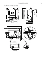
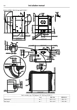
Page 31: ...Installation manual 31 6 5 Washer extractor type 1100 One door WP4 1100H Drawing 07100136 ...
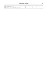
Page 53: ...Installation manual 53 ...
Page 66: ......
Page 67: ......
Page 68: ...Electrolux Professional AB 341 80 Ljungby Sweden www electroluxprofessional com ...

