


© ElectroCraft 2022
39
CPP-x06V48A-SA-CAN Drive User Manual
11
First Time Operation
To get started, proceed as follows:
1. Install ElectroCraft CompleteArchitect
Plus Universal Drive Configuration Tool onto user PC
and open the software window.
2. Connect I/O, motor phase and feedback wires to the drive. Make sure the Enable switch is in the
OFF position.
3. Supply required power to the drive (within the voltage and current range as specified in section
4) to operate the motor.
4. Establish communications between drive and PC software using the USB cable.
5. Use the configuration software to configure the drive settings. Refer to section 2 for details on
Software settings.
If the drive does not function, refer to Troubleshooting section 14.
12
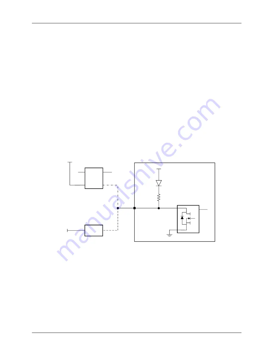
eBrake Control
The drive includes an output circuit that can be used to control an external electromechanical brake.
There are two options for this, as indicated below:
-
Option 1:
For high current applications, a relay or switch can be driven by the output.
-
Option 2:
For low current applications, the eBrake can be driven directly by the output.
DRIVE
Vin
5V
BAS1
6
590W
J5 Pin 6
24V
eBrake
Switch
eBrake
Coil
24V
OPTION 1
OPTION 2
Max current = 1.0A
Figure 33: eBrake Control Interface
Control parameters for the eBrake output are configurable in CompleteArchitect
TM
.
The user should consider the use case for the electromechanical brake and consult product requirements
for voltage, current and timing specifications. See section 4.3.7 for electrical specifications for eBrake
output circuit.


