


47
© 2006, Elektro-Automatik GmbH & Co. KG
EN
Using the power supply
6.12.4 Sequence related parameters
Sequence c
Function mode : U/I/P
Function mode of the power supply is displayed.
Seq. cycles
{1..254,
∞
}
Default:
1
= {1..254}
it will be repeated n times
=
∞
it will be repeated infinitely
P seq=
{0…P
nom
}
Default:
P
nom
The maximum power given here is affecting the whole
sequence.
Only with option „internal resistance“ (unlockable):
R seq= {
0
Ω
...10 % Ri
nom
}
Default:
R
nom
The maximum internal resistance given here is affec-
ting the whole sequence.
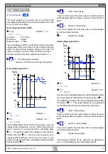
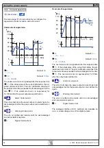
6.12.5 Defining the sequence points
Sequence points 0-4 {5-9} +
A sequence consists of 10 sequence points. A sequence point
consists of three values: the set values for U and I together
with the time
∆
t.
∆∆∆∆∆
t
=
{ 0…99:99h}
U[ V] =
{ 0… U
nom
}
I[ V] =
{ 0… I
nom
}
In order to understand how sequences are processed you
need to consider the start condition of every sequence cycle:
Set values at the start of the function
The function always starts with
U
set
= 0V and I
set
= 0A
Set values at reentrance into the sequence
If the sequence is repeated, the last processed sequence
point alters the start condition of the next sequence cycle.
Example: Sequence point 9 is set to the values 80V/50A/
250ms and the sequence is repeated, then the sequence
starts with 80V and 50A, but with the time that was set for
sequence point 0, for instance 500ms. After this time the
values of sequence point 0 are set.
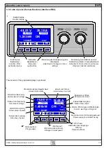
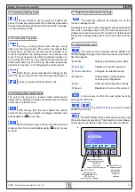
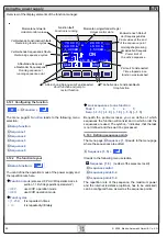
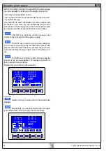
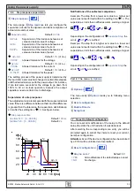
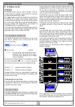
6.12.6 Display during the function run
Also see the overview on the previous page.
70.00 V
35.00 A
1400kW
Display of the actual values
On the left side of the display the actual values are shown in
small font. The status of the active control (CV/CC/CP) is
displayed to the right of the corresponding value.
The set values of the sequence point, which
will be reached after the sequence has been
processed, are shown on the right side of the
display
1
2/5
2
Status display of the function run
20.00 V
15.00 A
1500kW
The remaining repetitions of the function and the sequence,
as well as the sequence and the momentarily active sequence
point are displayed.
Function manager is halted or wasn’t started yet
Function manager is running
15:05 m
The elapsed time since the function gene-
rator was started is also displayed. The time display is stopped
when the function manager stops. The
STEP
,
RUN
or
GO
keys are used to run the function manager in several ways.
The time display will then continue to count.
{ON,OFF}
State of the power output
Besides the state of the power output an alarm, a warning or
a signal can be displayed.
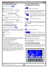
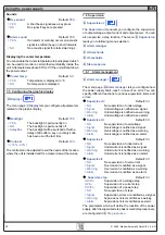
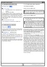
6.12.7 Controlling the function manager
The interactive control panel provides keys to control the
function manager. You can halt, continue, reset it to the
starting point or exit the function by using these keys.
ESC
ON
RUN
STEP
0.000kW
local
OFF
0.00 A
13.20 V
1.500kW
50.00 A
1
1/0
2
0.000 s
0.00 V