


41
© 2006, Elektro-Automatik GmbH & Co. KG
EN
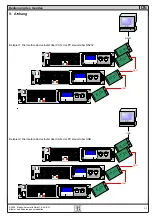
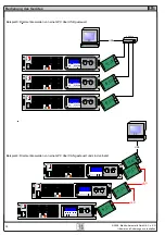
Using the power supply
4. General information
4.1 Prologue / Warning
This user instruction manual is intended for users who know
about the basic principles of a power supply and its appliance.
The operation of the unit shouldn’t be left to persons who are
unaware of the basic terms of electrotechnology, because
these are not explained in this manual. Inappropriate handling
and non-observance of the safety instructions may lead to a
damage of the unit or loss of warranty.
4.2 Mains connection / Grounding
The unit is grounded with the mains cord. Thus the unit may
only be operated at a mains socket with grounding contact.
This must not be interrupted with an extension cable without
grounding wire!
4.3 Cooling
The air inlets on the front and the air outlets at the rear side
have to be kept unimpeded and clean to ensure a proper
cooling.
Caution!
Hot air can emerge from the air outlets!
4.4 Transportation / Front handles
The handles on the front of the power supply
do not
serve
as carrying handles!
4.5 Disassembly
Warning!
The unit must not be opened and repaired by the
user.
When opening the unit or removing parts from the inside
with tools there is the risk of an electrical shock by dangerous
voltages. Open the unit only at your own risk and disconnect
it from the mains before.
Any servicing or repair may only be carried out by trained
personnel, which is instructed about the hazards of electrical
current.
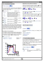
4.6 Temperature depending shutdown
The unit will shutdown the output because of too high internal
temperature. After cooling down it can switch on the output
automatically.
4.7 Case variant
The unit is built for desktop use. It can easily be modified by
the included kit to be fitted into 19“ racks/cabinets.
5. Installation
5.1 Visual check
After receipt the unit has to be checked for signs of physical
damage. If any damage can be found, the unit may not be
operated.
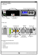
5.2 Mains connection
The mains connection is done with the included mains cord.
The plug is a 16A mains plug after IEC 320. The mains cord
has a length of about 1.5m and a cross section of 3 x 2.5mm².
The unit is fused with 5 x 20mm safety fuse (T16A), which is
accessible at the rear side.
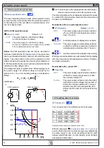
5.3 DC output at the rear side
The DC power output is located at the rear side of the power
supply, under a protective cover. The cover has first to be
removed in order to connect a load. The load cables are tied
using the M8 screws.
The output is NOT fused, but short-circuit-proof.
The cross section of the load cables has to be dimensioned
according to load current which is maximally drawn. We
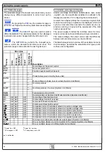
recommend:
at
100A
:
2 x 10mm
2
or at least 1 x 35mm²
at
50A
:
2 x 4mm² or at least 1 x 10mm²
at
25A
:
2 x 1mm² or at least 1 x 4mm²
at
15A
:
2 x 1mm² or at least 1 x 2,5mm²
to use
per cable
(flexible wire). The load cables should be
tied using appropriate ring cable lugs.
After connecting the load the cover has to be mounted again,
because the power supply generates dangerous voltage
>60V
DC
at the output terminals.
The outputs “+” and “-“ are not grounded, so that ONE of
them may be grounded if required.
5.4 DC output on the front / fuse
The DC output on the front is directly connected to the power
output at the rear side. The positive pole is lead over a T10A
safety fuse. This fuse is located at the rear side.
The sockets on the front are safety sockets, which are
dedicated to be used with laboratory Büschel plugs.
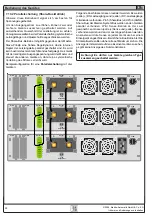
5.5 Remote sense feature
If the voltage drop over the load cables (max. 1.1 V per cable),
i.e. from the unit to the load, has to be compensated in order
to get the same voltage at the load which was set at the unit,
the remote sense terminals have to be wired. The unit is
then raising the output voltage by the amount of the voltage
drop, but only up to 1.1V per line.
Connect two wires, each from the positive and the negative
pole of the load, to the dedicated pins (Pin 1 (+ Sense) and
Pin 4 (–Sense) at the terminal
System Bus
. Recommended
cross section is 0,2mm
2
– 2,5mm
2
, flexible wire with cable
end sleeves.
If no voltage compensation is used, shorting jumpers between
Pin 1 to 2
and
Pin 3 to 4
have to be inserted. These jumpers
are already equipped by default.
(+) Sense must only be connected to (+) Output
and (–) Sense only to (–) Output. Else the unit might
get damaged .
!!!!!