Operating Instructions
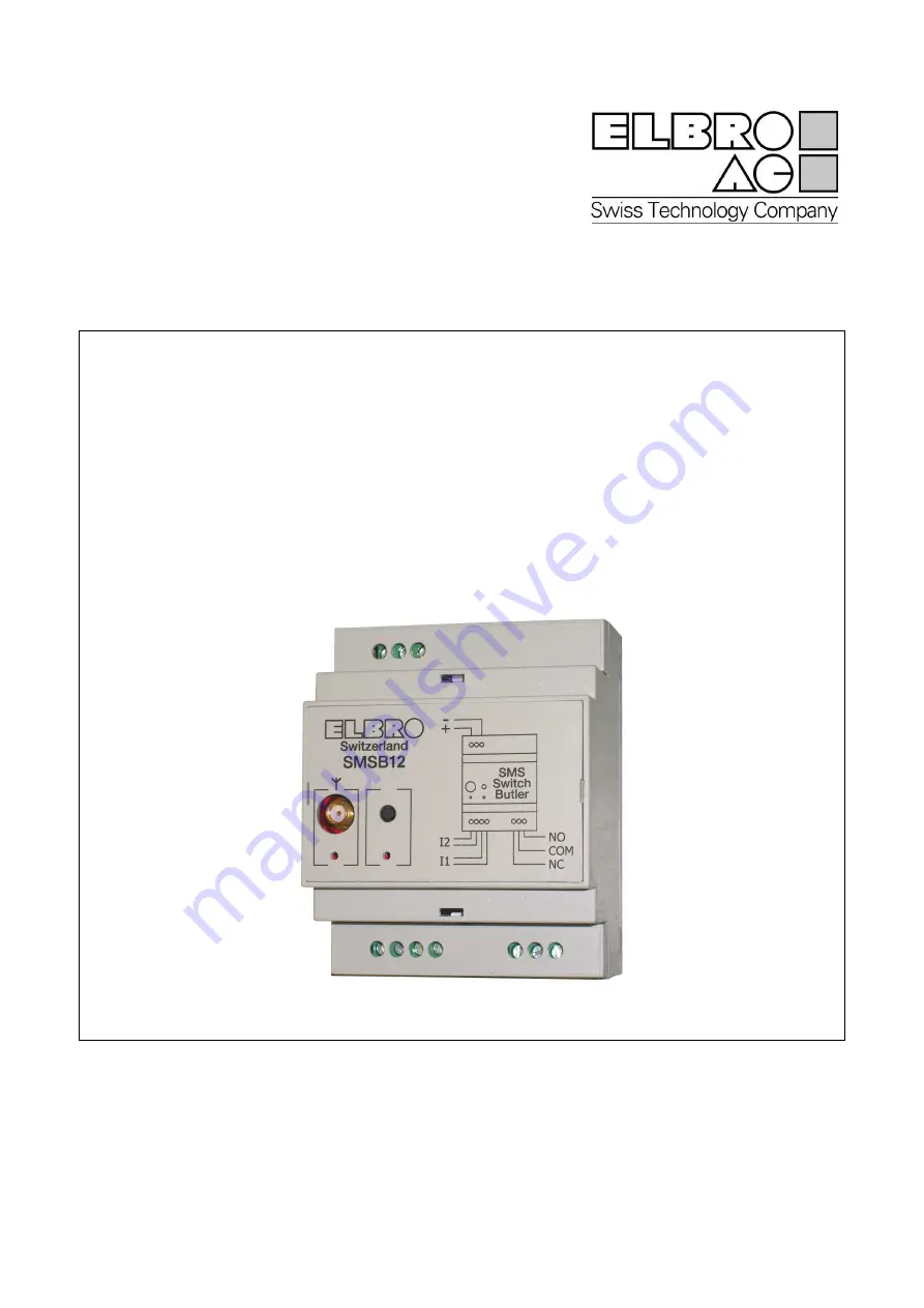
SMSB12, Firmware 3.0 SMSB12SW, Version 3.0
Page 1: ...Operating Instructions SMSB12 Firmware 3 0 SMSB12SW Version 3 0...
Page 2: ...SMSB12 SMSB12SW 2...
Page 3: ...and chemical plants The SMSB12 device operates by means of a radio signal no mobile telephone operator is ca pable of ensuring a connection at all times For this reason the SMSB12 device cannot be use...
Page 4: ...ling input line The SMSB12 device is able to receive commands sent via SMS messages or else through a sim ple voice call with zero cost The SMSB12 device is provided with specific configuration softw...
Page 5: ...the SMSB12 device the following degree of protection is to be ensured IP40 minimum degree of protection which must always be guaranteed IP54 protection to be guaranteed when using the device outdoors...
Page 6: ...apacity 10A 250V AC Never use cables with length exceeding 3m VOLTAGE FREE CONTACT IN PUTS It is possible to connect switches such as o Mechanical and electromechanical with suitable nameplate data 5V...
Page 7: ...an be used for Changing the output status of the device Displaying the reception level of the GSM network measured by the device RUN PROG toggle switch The RUN PROG switch allows o Starting the PROG m...
Page 8: ...nstall SMSB12SW Caution during installation of the SMSB12SW software it could be necessary to install Microsoft NET Framework 3 5 An internet connection is required Before running the program read the...
Page 9: ...SMSB12 device is protected by a four digit password de fined as system password The system password can be selected freely by the end user it must be used each time a command SMS message is sent Ente...
Page 10: ...associate from a minimum of zero 0 up to a maximum of five 5 SMS messages with each event The end user can choose freely the text of a signalling SMS message max length 160 characters and the destina...
Page 11: ...able to use the device proceed as follows 1 press the Upload data button in the Control Panel and wait for the confirmation window 2 select Connection Disconnect 3 disconnect the proprietary data cabl...
Page 12: ...t is omitted Notification SMS Format of a notification SMS is as follows GSM Remote Control Output X Inputs Y1Y2 Where X represents the output status o 0 contacts on COM NC o 1 contacts on COM NO Yi r...
Page 13: ...n LED is able to supply information regarding the cur rent status of connection of the device to the GSM network Guarantee Elbro devices are manufactured under strict quality control If nevertheless f...
Page 14: ...ts Network LED and multifunction LED Push button for manual switching of the output SMA antenna connector max conductor size which can be held in the terminals 2 5mm2 programming port Certifications E...
Page 15: ...eby Elbro AG declares that the device SMSB12 is in compliance with the essential requirements and other relevant provision of Directive 199 5 EC as having been designed in conformity with the re quire...
Page 16: ...SMSB12 SMSB12SW 16...