

All disclosures, notices and warranty conditions are being written on the back of the box.
Released on 25
th
of July, 2011.
Installation and mounting manual for EK-Supreme HF water block
This product is intended for installation only by expert users. Please consult with a qualified technician for installation. Improper installation may result in damage to your equipment. EK Water Blocks assumes no liability
whatsoever, expressed or implied, for the use of these products, nor their installation. The following instructions are subject to change without notice. Please visit our web site at
installation of this product please read important notice, disclosure and warranty conditions printed on the back of the box.
The barb hose fittings require only a small amount of force to screw them in; otherwise the high flow fittings might break. These fittings do not need to be tightened with much force because the
liquid seal is made using o-rings. The use of an algaecide and corrosion inhibitors is always recommended for any liquid cooling system.
STEP 1: GENERAL INFORMATION
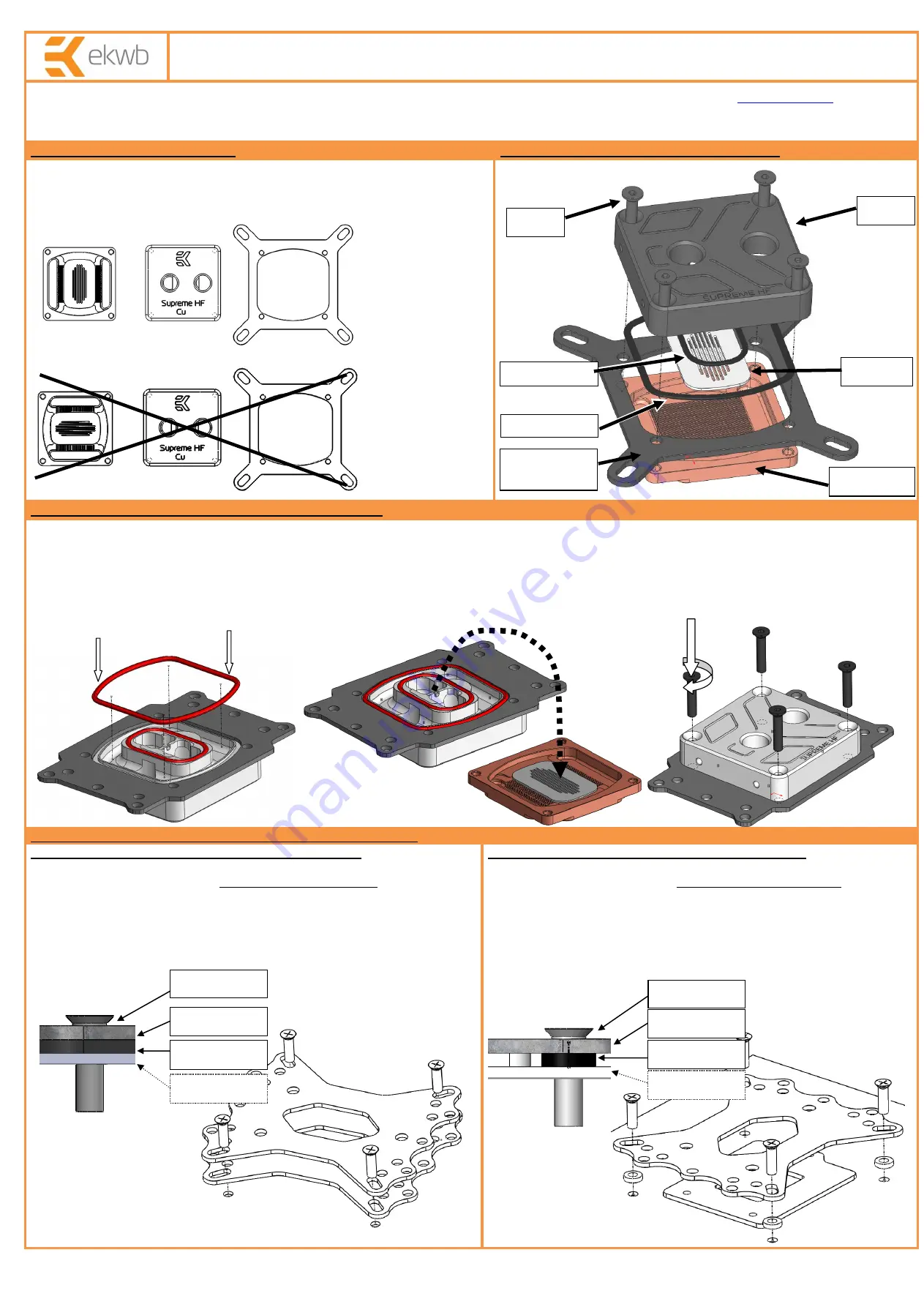
STEP 2: THE DESIGN OF YOUR WATER BLOCK
Please remove your motherboard from the computer to assure safest mounting
process in order to prevent any possible damages to your CPU and/or motherboard’s
circuit board (PCB). Sample picture bellow represents the correct orientation of block
and its flow path.
STEP 2.1 (optional): INSTALLING AMD MOUNTING PLATE
1) Place water block on an even surface and remove the four M4x20 DIN7991 screws attaching the top to the copper base using the enclosed 2.5mm allen key.
2) Put the top on it's back and place the AMD mounting plate on it.
3) Insert smaller gasket (28.3x1.78mm) into the milled groove and install larger gasket (54x2mm) into the gap between the mounting plate and plastic top
4) Carefully rotate the top/mounting plate assembly with both hands and place it on top of the copper base with installed jet plate.
5) Visually inspect if gaskets are seated correctly in the gaps. Repeat step #3 and #4 if necassery.
6) Screw in all four (4) M4x20 DIN7991 screws using the enclosed 2.5mm allen key.
STEP 3: INSTALLING BACKPLATE AND EASY MOUNT ASSEMBLY
STEP 3a: Intel LGA-775 and AMD socket motherboard:
1) Place motherboard on an even surface with front side facing down.
2) Install metal backplate together
with EPDM rubber washer
to the back of the
motherboard PCB and insert two (2) or four (4) M4x14 screw through all openings,
depending on the type of your motherboard
(see figure 1 and 2)
3) Carefully rotate motherboard assembly with one hand while holding the screws
and backplate with the other.
4) Install the rest of mounting system as shown
(see STEP 4)
STEP 3b: Intel LGA-1155/1156 socket motherboard:
1) Place motherboard on an even surface with front side facing down.
2) Install metal backplate together
with 2mm plastic standoffs
to the back
of the motherboard PCB and insert four (4) M4x14 screw through all four (4)
openings. Align the metal backplate to fit three LGA-115x ILM BP screws as the
metal backplate must sit on the LGA-115x ILM backplate
(see figure 1 and 2)
3) Carefully rotate motherboard assembly with one hand while holding the
screws and backplate with the other.
4) Install the rest of mounting system as shown
(see STEP 4)
M4x20
Intel LGA socket
mounting plate
Jet plate
Top
Copper base
CORRECT
INCORRECT
Gasket
54x2 mm
Gasket
28.3x1.78
EPDM rubber
M4x14 screw
Metal backplate
Motherboard
PCB
figure 1
figure 2: Isometric view of backplate assembly using EPM rubber washer – valid for
Intel LGA-775- and AMD socket motherboard. Picture is for reference only!
figure 1
figure 2: Isometric view of backplate assembly for LGA-1155 & -1156
Step #2 and #3:
Step #4:
Step #5 and #6:
Metal backplate
Motherboard
PCB
M4x14 screw
2mm standoff


