background image

9     

Adjusting the ACTIVATION Zone


108842 A 

CHAPTER 7: 

ADJUSTING THE ACTIVATION ZONE 

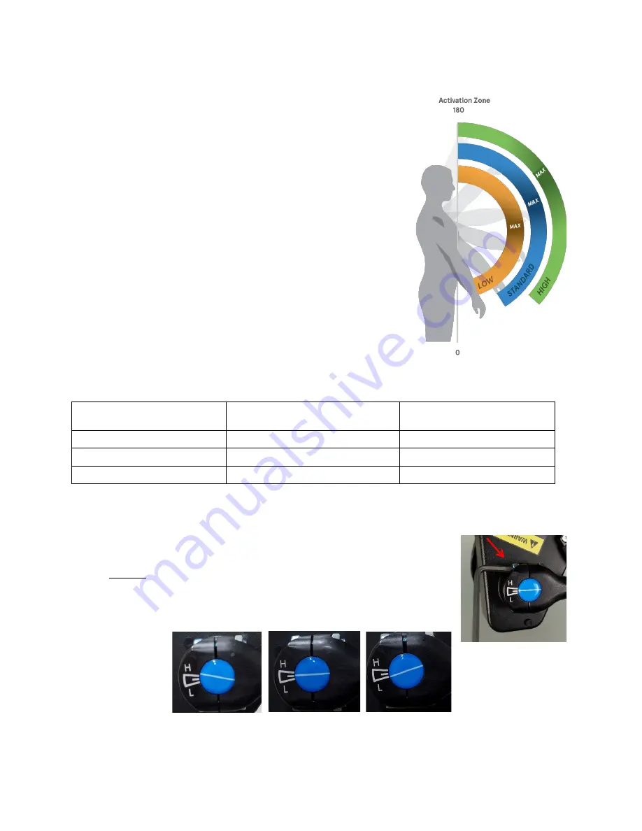
EVO features an adjustable “activation zone”. The activation zone is the area in 

which EVO provides support to the operator’s arms while performing in-front and 

overhead work.  
 
EVO offers three different activation zone settings:  


H (high) setting (usually for overhead work) 


“Standard” setting (marked by the middle line) 


L (low) setting (usually for in-front work). 

 
The Figure shows how each setting changes the activation zone starting points 

and max support areas. 
 
The table below lists the approximate angle (from 0° fully lowered position) for 

each activation zone starting point and max support point. 


Table 5: Activation and Support Angles 


As described in the following procedure, adjusting the activation zone must be done when the EVO is not being worn. 

Personal comfort and preference should always guide which activation zone setting to use for each arm.  

To adjust the activation zone: 

1.  Secure one arm of the EVO in the down (lowered) position. Enable that actuator 

by flipping the switch to the ON position. 

2.  Carefully guide the EVO arm upwards to the fully raised (up) position.  

3.  Use T25 driver to loosen the top socket head cap screw on the end link. Loosen 

the screw approximately one-quarter turn. 

4.  Using the end link graphic as a guide, adjust the dial to H (high) or L (low) setting 

as desired; default adjustment will be set at the “standard” setting (middle line). 


Activation Setting 

Degree (from 0°) for Starting 

Support Point (approximate) 

Degree (from 0°) for Max 

Support Point (approximate) 

Low Setting 

15° 

105° 

Standard Setting 

25° 

115° 

High Setting 

35° 

125° 

Figure 10: Activation Zone Settings 

Figure 12: High, Standard, and Low Activation Zone Settings 

Figure 11: Loosening 

End Link Screw 

Summary of Contents for EVO Exoskeleton

Page 1: ...OPERATING MANUAL EVO Exoskeleton ...

Page 2: ...onics the Ekso Bionics Icon are trademarks of Ekso Bionics Inc Patents Patents Pending For a list of patents and patents pending refer to the Ekso Bionics website Disclaimer Potentially serious injury may occur in connection with the use of Ekso EVO Ekso Bionics Inc shall not be liable for any injury or damage suffered by any person either directly or indirectly as a result of the use or repair of...

Page 3: ...tments 4 MEASUREMENT AND FITTING INFORMATION 4 Fit Guide Tables 5 CHAPTER 4 Donning and Doffing EVO 6 Donning EVO 6 Doffing the EVO 7 CHAPTER 5 Turning EVO On and Off 7 Turning EVO On 7 Turning EVO Off 7 CHAPTER 6 Installing and Changing Actuator Springs 8 EXO Actuator Spring Support Levels 8 Installing Actuator Springs 8 CHAPTER 7 Adjusting the ACTIVATION Zone 9 CHAPTER 8 Fit Adjustments 10 CHAPT...

Page 4: ...ucture allowing unrestricted airflow and leaving plenty of room for a fall harness Minimized body contact EVO is designed to only contact the user s body where it is absolutely essential while still staying firmly in place during use The result is more comfortable and cooler to wear than even a backpack especially in hot environments Adjustable high force actuator EVO s actuators are proven to be ...

Page 5: ...h EVO are identified in the following drawing and table Component Identifier Component Name A Arm Cuff Plate B Actuator Spring C ON OFF Switch and Tether D Actuator Activation Zone Indicator E Actuator F Link Assembly G Torso Pad Support H Torso Tube I Waist Plate J Belt Extensions A B C D E F G H I J ...

Page 6: ...stments may be required Belt size Measure the distance around your back between your 2 hip pelvic bones the iliac crest Be sure to make the measurement over your typical work clothes Measurement ___________inch cm Figure 1 Hip to Hip Measurement Arm Cuff size Measure the circumference of your bicep at the widest point in a relaxed position Be sure to make the measurement over your typical work clo...

Page 7: ... Slot Setting in cm S M WING 1 19 22 5 48 3 57 2 2 22 5 24 57 2 61 3 24 25 5 61 64 8 4 25 5 27 64 8 68 6 5 27 28 5 68 6 72 4 L XL WING 1 28 5 30 72 4 76 2 2 30 31 5 76 2 80 3 31 5 33 80 83 8 4 33 34 5 83 8 87 6 5 34 5 36 87 6 91 4 Torso Length Lower Torso Tube Size Upper Torso Tube Position in cm SMALL TUBE 1 14 14 6 35 5 37 2 14 6 15 2 37 38 5 3 15 2 15 7 38 5 40 4 15 7 16 3 40 41 5 5 16 3 16 9 4...

Page 8: ...ing the EVO over your shoulders 3 Secure the hip belt using the buckle Position the hip pads so they are covering your hip bones then tighten the belt by pulling on the webbing loops inward The belt should be tight enough to avoid shifting but not uncomfortable 4 Slip each arm through the arm cuff Use the pull handle strap to fully open the cuff to allow for easier insertion 5 Tighten the three st...

Page 9: ...F switch with tether located on the actuator housing Moving the switch to the ON position activates the spring support of the actuator Take care if activating the switch while the EVO is not being worn as the arm can raise up in an uncontrolled manner Turning EVO On To turn EVO on the operator must keep their arm fully down by their side The switch on the actuator can then be flipped to the ON pos...

Page 10: ...ort Level 3 5 7 lb 7 9 lb 9 12 lb 2 2 3 1 kg 3 1 4 0 kg 4 0 5 4 kg When sizing EVO Ekso Bionics recommends beginning with a lower force spring and changing to a higher force level as needed Installing Actuator Springs Installing changing the actuator springs should be performed when the EVO is not being worn To change the actuator springs follow the steps below 1 Secure one arm of EVO in the lower...

Page 11: ...ion zone must be done when the EVO is not being worn Personal comfort and preference should always guide which activation zone setting to use for each arm To adjust the activation zone 1 Secure one arm of the EVO in the down lowered position Enable that actuator by flipping the switch to the ON position 2 Carefully guide the EVO arm upwards to the fully raised up position 3 Use T25 driver to loose...

Page 12: ...roperly positioned and tightened Adjust torso length if needed The arm cuff slides up and down on your arm The arm cuff straps are likely too loose Readjust and tighten arm cuff straps as needed The webbing straps are digging into your waist Check the position of the hip pads and adjust to ensure they are centered over your hip bones The arm cuff is too tight no matter how it is adjusted If wearin...

Page 13: ... in the actuator base DO NOT USE TOOLS TO TIGHTEN OR LOOSEN ACTUATOR SPRINGS Daily Soft goods are damaged Examine all soft goods arm cuffs torso pads hip pads and lumbar pad for wear or damage Examine both sides of each soft good and all stitching for visible damage discoloration or deterioration manually inspect the material with fingers to feel for wear such as tearing fraying unevenness or loos...

Page 14: ...Included Hip Belt 1 108832 Included Large Belt Extensions 4 108701 Large Included Arm Cuffs 8 108659 Left S 108658 Right S 108661 Left M 108660 Right M 108663 Left L 108662 Right L 108769 Left XL 108768 Right XL One Pair Included LEFT RIGHT Actuator Springs 3 Level 1 107199 Level 2 107200 Level 3 107201 One Set 2 Springs Included shipped in storage bag pockets EVO Quick Start Guide 1 108848 Includ...

Reviews: