32
Service Guide: Fiery Central Solo for KM
Service Procedures
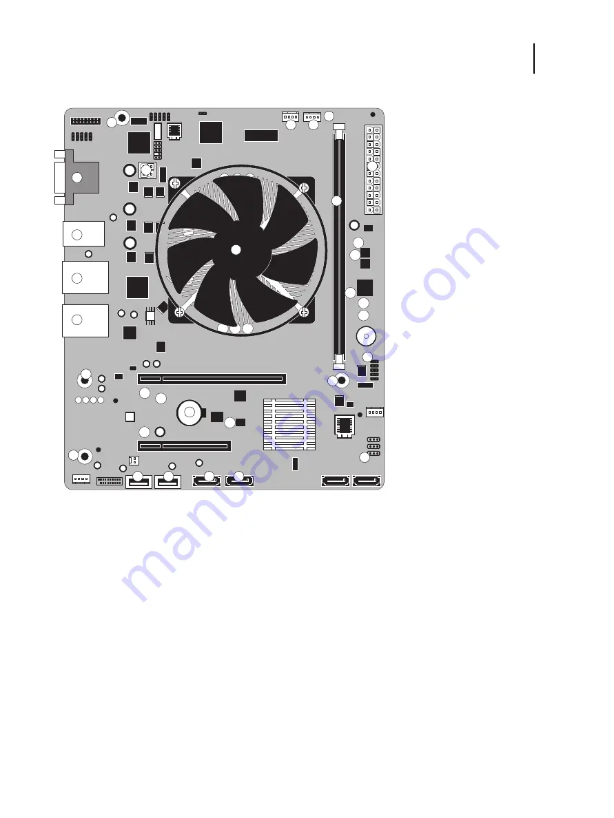
Figure 14:
Diagram of the FC Solo motherboard
1
4-pin power connector (J18)
7
CPU FAN (J16)
13
Battery
2
DVI/VGA ports
8
24-pin power connector (ATX24P-1)
14
Front panel USB 2.0 port (USB_A2)
3
USB 2.0 ports
9
CPU and cooling assembly
15
UIB cable (USB_A1)
4
RJ-45 Network port/USB 2.0 ports
10
DIMM slot
16
DVD drive connector (SATA_6G_0)
5
RJ-45 Network port/USB 3.0 ports
11
Reset and Power button cable (J15)
17
HDD connector (SATA_6G_1)
6
Chassis fan (J21)
12
Clear CMOS Jumper (J4)
MS
(Mounting screws)
Note:
Any connectors not listed are not used.
1
2
8
10
MS
MS
MS
MS
MS
3
4
5
6
7
9
11
12
13
14
15
16
17


