background image

40

ENGLISH

USER INSTRUCTIONS

USER

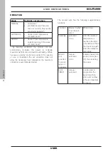
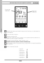
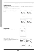
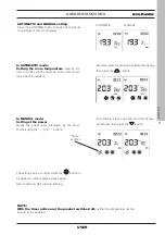
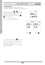
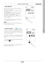
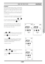
- FAN ADJUSTMENT

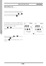
The setting can be made with the stove turned OFF or ON.
If the backlight is switched off, it can be activated by pressing any button.

Then by pressing the button 

 or 

 SET flashes 

and instead of the environment Set, the indication of the 
number of the fan being edited appears (F1). 

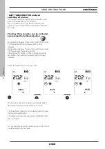
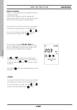
The fan speed can be increased or decreased with 

 or 

 in the following sequence:

1 -2 - 3 - 4 - 5 - AUTO - for the front fan (1)

OFF-1-2-3-4-5- AUTO for ducted fans (2 and 3)

with button 

with button 

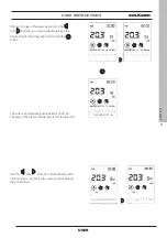
You can confirm the setting with the  

 button and 

then move to the next fan, if present (only for PLUS 

ducted versions), otherwise you can exit the fan setting 

page and “SET” will stop flashing.
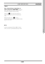
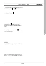
Wait 5" without pressing any button to exit the fan setting, 
and SET will stop flashing.

Summary of Contents for CHERIE 11 EVO

Page 1: ...EN Installation use and maintenance page 2 PELLET STOVE For all updates visit www edilkamin com CHERIE 9 EVO Air Tight C CHERIE 11 EVO Air Tight C ...

Page 2: ...NO Rating plate reference CHERIE 9 EVO Air Tight C Declaration of Performance DoP EK no 209 CHERIE 11 EVO Air Tight C Declaration of Performance DoP EK no 210 Moreover the company hereby declares that the above mentioned wood burning pellet stoves satisfy the requirements of the following European directives 2014 35 EU Low Voltage Directive 2014 30 EU Electromagnetic Compatibility Directive 2011 6...

Page 3: ...ot always strictly refer to your specific model and are not binding in any way MEANING OF SYMBOLS In some parts of the manual the following symbols are used INFORMATION failure to comply with these requirements will compromise product use PLEASE NOTE carefully read and understand the message in question since failure to follow the instructions in it could cause serious damage to the product and pu...

Page 4: ...uc Reduz Reduite Ridotta Nominal Rated Nominale Nominale Poele a circuit de combustion étanche DTA nĀ 14 2 15 2083 I 20045 Lainate MI via Mascagni 7 3 kW Kg h bar kW kW kW Heat input Thermische Leistung eingefuhrt Puissance calorifique introduite Potenza termica introdotta Nominal heat output Gesamt Nennleistung Puissance normal total Potenza nominale totale Boiler output Leistung Wasserseitig Pui...

Page 5: ... CLEANER WHILE IT IS HOT You could damage the vacuum cleaner and risk letting smoke into in the room cleaning of the fume duct with various substances DO NOT ATTEMPT HOME GROWN CLEANING SOLUTIONS USING INFLAMMABLE PRODUCTS Risk of fire or blowback cleaning of the glass while hot or using unsuitable cleaning products DO NOT CLEAN HOT GLASS WITH WATER ONLY USE RECOMMENDED GLASS CLEANING PRODUCTS The...

Page 6: ...the national and local regulations In particular this in not an exhaustive list refer to the EN 13384 EN 1443 EN 1856 EN 1457 standards and to all local regulations 116 20 A Ø 8 cm B Ø 8 cm Ø 8 cm smoke outlet Ø 13 cm coaxial 63 11 19 19 5 5 11 DIMENSIONS cm Cherie 9 Evo Air Tight C A possible ducted air outlet or diverter position Cherie 11 Evo Air Tight C A B ...

Page 7: ... 2 1 0 8 kg h Tank capacity 18 kg Draw 10 10 Pa Autonomy 9 23 hours Heatable volume 240 m3 Smoke duct diameter 80 mm Weight including packaging steel ceramic soap stone 216 218 250 kg Energy efficiency class in accordance with EU regulation 2015 1186 Classes A G A TECHNICAL DATA FOR SIZING THE FLUE which must in any case satisfy the requirements of this sheet and the installation instructions CHER...

Page 8: ...on 2 6 0 8 kg h Tank capacity kg Draw 11 10 Pa Autonomy 7 23 hours Heatable volume 295 m3 Smoke duct diameter 80 mm Weight including packaging steel ceramic soap stone 218 220 252 kg Energy efficiency class in accordance with EU regulation 2015 1186 Classes A G A TECHNICAL DATA FOR SIZING THE FLUE which must in any case satisfy the requirements of this sheet and the installation instructions CHERI...

Page 9: ... kW NO NO F 4 2 5 CC 2 5 yes F 2 7 0 up to 2022 F 2 7 0 from 2022 NO NO with distance control option yes F 3 1 0 up to 2022 F 3 1 0 from 2022 Contact details Name and address of the manufacturer www edilkamin com EDILKAMIN S p A mail edilkamin com Via Mascagni 7 Legal Representative 20045 Lainate MI ITALY Paolo Gusella Other control options multiple selections possible room temperature control wit...

Page 10: ...03 kW NO NO F 4 2 3 CC 2 5 yes F 2 7 0 up to 2022 F 2 7 0 from 2022 NO NO with distance control option yes F 3 1 0 up to 2022 F 3 1 0 from 2022 Contact details Name and address of the manufacturer www edilkamin com EDILKAMIN S p A mail edilkamin com Via Mascagni 7 Legal Representative 20045 Lainate MI ITALY Paolo Gusella Other control options multiple selections possible room temperature control w...

Page 11: ...h suitable equipment and in observance of safety regulations Do not turn the package over and handle all parts requiring installation with care INSTALLER The packaging may vary in the various destination countries for regulatory and transport related reasons THE DRAWINGS ARE PURELY INDICATIVE AND ARE USEFUL FOR ASSEMBLY PURPOSES BUT DO NOT ALWAYS REFER TO THE SPECIFIC MODEL DEFLECTOR The product i...

Page 12: ...EFORE HAVING OPENED THE DOOR REMOVED THE FRONT PANEL lift it to detach it LOOSENED THE SCREWS FASTENING IT TO THE PALLET THE DRAWINGS ARE PURELY INDICATIVE AND ARE USEFUL FOR ASSEMBLY PURPOSES BUT DO NOT ALWAYS REFER TO THE SPECIFIC MODEL screws front panel screws with plate on the rear ...

Page 13: ...e top List the cover of the pellet to open it Loosen the screws indicated below Pull the top towards yourself to slot it out and lift it 2 Assembling and fitting the side panels onto the structure On each of the sides undo the metal support screws unhook the metal support and remove it screws for fitting the metal supports metal support STEEL CLADDING INSTALLER screws ...

Page 14: ...them together shaped polystyrene piece NOTE The curving of the side panels may not perfectly coincide with the curving of the brackets Therefore use your hands to make the panel fit to the bracket before tightening the screws Do not use any tools so as to avoid the risk of scratching the side panel Once the position of the side panel is correct tighten the screws while keeping the side panel in po...

Page 15: ...side NOTE For a better understanding of the position the image below shows the components in a vertical position but we nevertheless recommend that you work in a horizontal position on top of the shaped polystyrene piece INSTALLER screw nut bracket bracket nut screw black toothed washer toothed washer black toothed washer toothed washer ...

Page 16: ...se your hands to make the panel fit to the bracket before tightening the screws V Do not use any tools so as to avoid the risk of scratching the side panel Once the position of the side panel is correct tighten the screws while keeping the side panel in position This will also avoid any interference with the door V V V Make sure that the central spacer has been placed in the cut on the metal suppo...

Page 17: ...ews securing the metal supports STEEL CLADDING screws for fitting the metal supports INSTALLER 3 Assembling and mounting the top Place the cast iron inserts on the upper part of the top and screw them on from below as shown in the figure Insert the top and screw it to the structure as explained in point 1 screws screws screws ...

Page 18: ... the structure 1 Remove the top List the cover of the pellet to open it Loosen the screws indicated below Pull the top towards yourself to slot it out and lift it 2 Assembling and fitting the side panels onto the structure On each of the sides undo the metal support screws unhook the metal support and remove it screws for fitting the metal supports metal support screws ...

Page 19: ...ped polystyrene piece and proceed as follows INSTALLER 2 1 Bring the ceramic side panels together 1 shaped polystyrene piece Position the two adjustment brackets on the ceramic piece and apply the screws without tightening them adjustment bracket c adjustment bracket c screw TE M4x10 b washer D5 a ...

Page 20: ...he correct position is the point where the bracket profile meets with the metal support Tighten the screws that fix the brackets to the metal profile metal support Position the small bracket with the cage nut on the metal support and screw on with the supplied M4 2x9 5 screw The drawing shows the left side panel for the location of the small adjustment bracket metal support screw TE M4x10 b washer...

Page 21: ...e template for fitting the side panels Respect the distances between the metal support and the ceramic piece as in the drawing 60 and 70 mm The 70 mm measurement can also be taken from the template position CERAMIC CLADDING INSTALLER template Do not force the screw into the threaded bushing it may break ...

Page 22: ... screws for fitting the metal supports POSSIBLE ADJUSTMENTS The brackets allow internal external adjustment The slots allow forward backward adjustment in the top part The small brackets allow forward backward adjustment in the bottom part The adjustment screw on the small bracket is used to secure the side panel and to further adjust its position bracket small bracket bracket slots ...

Page 23: ...LLER 3 Assembling and mounting the top Place the ceramic inserts on the upper part of the top and screw them on from below as shown in the figure Insert the top and screw it to the structure as explained in point 1 screws screws screws ...

Page 24: ... indicated below Pull the top towards yourself to slot it out and lift it 2 Assembling and fitting the side panels onto the structure On each of the sides undo the metal support screws unhook the metal support and remove it The support will not be used screws for fitting the metal supports metal support screws ...

Page 25: ...ts and re tighten the screws securing the metal supports screws for fitting the metal supports 3 Assembling and mounting the top Place the cast iron inserts on the upper part of the top and screw them on from below as shown in the figure Insert the top and screw it to the structure as explained in point 1 screws screws screws ...

Page 26: ...ountry check whether there are any particular installation conditions allowed for sealed stoves installation conditions allowed for sealed stoves Checking the suitability of the room of installation The room must have a volume of at least 30 m3 The floor must be able to bear the weight of the product and its accessories see the note in the paragraph on heat protection Level the appliance In Italy ...

Page 27: ... sky be made of material rated fire reaction class A1 per UNI EN 13501 or analogous national regulations be appropriately certified with a suitable chimney plate if made of metal maintain the same cross section throughout it may only vary immediately after the outlet not along the flue THE SMOKE DUCT THE SMOKE DUCT In addition to the general requirements for the fume duct and the flue the fume duc...

Page 28: ... other must extend beyond the back flow zone in Italy refer to UNI 10683 point 6 5 8 must allow for maintenance of the chimney EXTERNAL AIR INTAKE In general we suggest two alternative ways for ensuring a proper flow of indispensable combustion air Indirect air intake Install an air outlet at floor level with an effective surface area net of the screen or other protections of at least 80 cm2 10 cm...

Page 29: ... the combustion air into the external circular ring This type of installation only needs one hole in the wall instead of having one hole for the air intake and one for the smoke discharge stufa scarico fumi sopra presa aria sopra con uso coassiale Examples of possible installations For the smoke discharge conditions on roof etc check local regulations for sealed pellet stoves Upper coaxial fumes d...

Page 30: ... air diverter kit output we recommend purchasing the air diverter kit A appearing in the price list A appearing in the price list To duct the warm air exiting the rear there are several To duct the warm air exiting the rear there are several optional accessories available at your dealer optional accessories available at your dealer The adjustment process is described in the The adjustment process ...

Page 31: ... ISO 17225 2 standard or similar local regulations envisaging for example products with the following envisaging for example products with the following characteristics characteristics diameter 6 mm diameter 6 mm length 3 4 cm length 3 4 cm humidity 10 humidity 10 For reasons relating to safety and environmental For reasons relating to safety and environmental protection DO NOT burn plastic painte...

Page 32: ...ovided if for reasons of use or installation the set ventilation does not allow the necessary heat dissipation the maximum ventilation is automatically started The product also has the following supplementary functions Function Modes in which it can be acti vated What it does Stand By automatic crono when the desired temperature is reached the prod uct switches off and then back on again when the ...

Page 33: ...oduct The Mind APP T M Ä useful for all functions at home with direct connection or outside the home with internet connection and registration If necessary a few functions can also be managed from a SAVE PANEL placed on the product T M Ä By purchasing the Edilkamin optional elements VOICE CONTROL SYSTEMS Alexa or Google Home USER INSTRUCTIONS USER ...

Page 34: ...aller or remote On Off or Thermostat Thermostat on home automa tion contact Thermostat in place of the ambient probe on the elec tronic board ACTION The product turns on off without any modulation the product modulates goes into stand by and turns on off terminal block example example NOTE The connections must be made by qualified personnel with the electricity disconnected More info for installer...

Page 35: ...and after a further 10 the display switches off If any button is pressed with the display on the counter resets If any button is pressed while the display is off the display and the backlighting will switch on and the counter will reset This only refers to the remote control not the product itself In normal use the remote control s batteries should last a year This duration is for illustrative pur...

Page 36: ...roblem on the board In any case contact the TAC The relative function is active Relax airKare EasyTimer Crono EasyTimer and Crono cannot be activated simultaneously Reserve indicator It switches on if the function is active The arrows switch on in sequence to signal that the tank must be filled Presence of flame and stove power USER INSTRUCTIONS FOR USE REMOTE CONTROL POWER ON POWER LEVEL 1 POWER ...

Page 37: ...ET POINTS Setting of the various SET POINTS temperature power fan speed Automatic or Manual mode the product s air power depends on the room temperature or is set by the user Indicates that the product has switched off after the target has been reached with stand by mode active DOES NOT indicate that the function is enabled FAN OFF SPEED 1 SPEED 2 SPEED 3 SPEED 4 SPEED 5 AUTOMATIC Setting Indicate...

Page 38: ...y wait without taking any action During switch off the display shows the message SHUTDOWN If time programming is active the status and programming are displayed alternately 3 seconds on the status bar During the switch on the display will show the status CLEANING SWITCH ON etc The ON OFF button is used to manually start the on or off phase SHUTDOWN ...

Page 39: ...mple press any button and the display will activate then press the button flame symbol The setting can be confirmed with the button or by waiting 5 without pressing any button After confirming SET will stop flashing AUTOMATIC and MANUAL setting Press the AUTO MAN button to switch from manual to automatic mode or conversely Example press a button and activate the display then press the button NOTE ...

Page 40: ...r of the fan being edited appears F1 The fan speed can be increased or decreased with or in the following sequence 1 2 3 4 5 AUTO for the front fan 1 OFF 1 2 3 4 5 AUTO for ducted fans 2 and 3 with button with button You can confirm the setting with the button and then move to the next fan if present only for PLUS ducted versions otherwise you can exit the fan setting page and SET will stop flashi...

Page 41: ... without pressing any button to exit the fan setting and SET will stop flashing even if there are other fans Pressing the button to confirm will take you to the next fan Fan 3 if present Waiting 5 without pressing any button takes you back to the home page with the modified SET Pressing the button to confirm will take you to the next fan Fan 2 if present Pressing the or button modifies the fan spe...

Page 42: ...relative room set point and display the room temperature After setting the installation room temperature or with the room power in manual mode wait 5 without pressing any button and SET will flash then you will exit the settings page Otherwise if you confirm with the button you can set the room set point for zone 2 if the probe is present and active indicated on the bottom bar Press OK to move to ...

Page 43: ...t reduces its power output and after a few minutes switches the fan off too NOTE While the Relax function is active it is not possible to increase the power to level P5 USER AIRKARE FUNCTION This function is available as a standard feature on certain models and as an optional feature on other models check which model you have The function if available can be activated with the product either on or...

Page 44: ... time can be set with hour intervals By activating the Easy Timer function with the product off the user sets the switch on time Pressing the OK button or after 5 without pressing any button the countdown will start with 5 minute intervals The Easy Timer function can be deactivated by press ing the dedicated button The display will show an arrow above the button and the countdown To vary the timer...

Page 45: ...room temperature otherwise at the power setting Pressing the button allows for switching from Crono in Temperature and Crono to Power and vice versa Briefly pressing the button activates or deactivates the timer programmed in advance from the app or remote control NOTE The timer is programmed from the MENU The timer button is only used to activate deactivate the function ...

Page 46: ...ions from the techni cian Therefore we do not report the complete explana tion in this document DISPLAY INFO SOFTWARE DATA ALARMS PELLET FALL PELLET SENSOR TECHNICAL MENU SET TEMPERATURE The set point digits contain the progressive number of the menu item while the status bar includes the description of the menu item in large letters NOTE Depending on the version the order of the items may vary To...

Page 47: ...s with the and buttons and enter the item with the button After entering the Stand by function the display will show the name of the function on the first line of the status bar and the current value on the second line OFF if deactivated ON if active The and buttons can be used to modify the value from Off function deactivated to On activated and the button can be used to confirm Pressing the butt...

Page 48: ...S PELLET LOADING Allows you to load pellets after the pellet tank has been completely emptied Useful for the technician during the initial start up Available only in the OFF status Any attempt to activate the function in other statuses will not be allowed To access the function from the main menu as indicated in the Menu section above press the MENU button You can scroll the menu items with the an...

Page 49: ... RH shows the start of the time slot Use the and buttons to scroll the time with 1 2 hour steps by moving the cursor and displaying the pre set level Choose the day of the week by scrolling the and buttons you will simultaneously see the programme for that day and confirm with the button OK SAVE BUTTON ...

Page 50: ...can be used to modify the temperature levels OFF T1 and T2 or the power levels OFF P1 and P5 After reaching 23 30 you must go backwards If you shift by pressing and holding the or buttons for more than 2 you copy the previous level onto the next level with a 1 2 h frequency per second The level can be copied also with backward shifts ...

Page 51: ...he main page USER INSTRUCTIONS The copied day of the week flashes and you can shift to the next day using the and buttons USER NOTES The switching on and off of the product can be forced with the timer active by pressing the ON OFF button for 2 Only with the Stand by function active will the product switch off once the set temperature has been reached Confirm with the button ...

Page 52: ... is the lowest temperature T2 the highest Use the and buttons to move to set point T2 setting To access the function from the main menu as indicated in the Menu section above press the MENU button You can scroll the menu items with the and buttons and enter the item with the button Modify the values with the and buttons and confirm with the button Pressing the button automatically takes you to the...

Page 53: ...e MENU button You can scroll the menu items with the and buttons and enter the item with the button After entering the Date Time function the display will show the name of the function on the first line of the status bar and the current value of the first setting 12 24 hours on the second line You can switch from 12 to 24 hours using the and buttons and confirm with the button You reach the AUTO S...

Page 54: ...enu as indicated in the Menu section above press the MENU button You can scroll the menu items with the and buttons and enter the item with the button Modify the language using the and buttons then exit and confirm with the button Pressing the button automatically takes you to the first level The following functions must be taken into account only following indications from the technician Therefor...

Page 55: ...ttons and and confirm with OK button STBY BRIGHTNESS Indicates the backlight percentage of the display be fore entering energy saving mode TIME ON Indicates the time the display remains illuminated STANDBY TIME Indicates the amount of time the display remains illumi nated before entering power saving mode BEEP Allows to enable an acoustic signal when the buttons are pressed OFF if deactivated ON i...

Page 56: ...agnostic meaning of the messages and values and may ask you to read them to him her if you experience problems INSTALLER Pressing the button automatically takes you to the first level To access the function from the main menu as indicated in the Menu section above press the MENU button You can scroll the menu items with the and buttons ...

Page 57: ...only under the guidance of the Technical Assistance Centre Leonardo indicates the target value set and read To be read only under the guidance of the Technical Assistance Centre Fan1 indicates the output voltage To be read only under the guidance of the Technical Assistance Centre Ignition plug spark plug indicates whether the ignition component is on or off Useful in the ignition phase to underst...

Page 58: ...icates the firmware version of the electronic board basic board the firmware version of the control panel the database associated by the Technical Assistance Centres with the products To be read only under the guidance of the Technical Assistance Centre ...

Page 59: ...USER INSTRUCTIONS To access the function from the main menu as indicated in the Menu section above press the MENU button You can scroll the menu items with the and buttons and enter the item with the button Pressing the button automatically takes you to the first level DATA N ACC 236 DATA WORKING HOURS 236 ...

Page 60: ...ian The meaning of the abbreviations is in the dedicated paragraph The alarms are arranged from the most recent to the oldest Exit with the button PELLET SENSOR Allows you to set ON or OFF of the pellet level sensor PELLET FALL Allows to set the auger motor in continuous cycle or in steps To be carried out ONLY UNDER THE GUIDE OF A TECHNICIAN PELLET FALL PELLET FALL CONTINUES SENSOR ...

Page 61: ...ct to seize up Information on how to use these functions is only available to technicians in the appropriate web area After entering the Technical Menu the first item FLAME TYPE will appear You can enter the Flame Type setting using the button while the and buttons can be used to modify the correction value Pressing the button automatically takes you to the first level FLAME TYPE for the TECHNICIA...

Page 62: ...e Pellet Type setting with button and the value can be modified with button and Use the button to exit and return to the Technical Menu In correct installation conditions with the Service Centre parameters appropriately adjusted with quality pellets the pellet load is adjusted MEDIUM HIGH LOW USER INSTRUCTIONS INSTALLER ...

Page 63: ...up to the item PARAMETERS You enter the Parameters with button the first parameter is displayed Scroll through the parameters with and and the value can be modified with buttons and If you entered the Technician Menu with the Installer Password only the Installer parameters appear otherwise all the parameters appear ...

Page 64: ...o activate the speed of the ducting fan at maximum ON OFF NUMBER OF FANS enables or disables the possibility for the end customer to operate the fan if present ROOM INPUT allows to choose which item the end customer reads and adjusts on the Home display It depends on the type of plant PROBE room probe standard in the product THERMOSTAT enables the thermostat which can be installed in place of the ...

Page 65: ...65 ENGLISH SET TEMPERATURE Allows the correction of the reading of some temperature probes To be carried out ONLY UN DER THE GUIDE OF A TECHNICIAN ADJ ROOM1 ADJ TEMP RADIO USER INSTRUCTIONS INSTALLER ...

Page 66: ... product is controlled via the SAVE PANEL FUNCTIONS To switch on the product press the On Off button for a few seconds To set the power level with the product on press the power button once Pressing it repeatedly will cause the power to increase with the following setting appearing on the display P1 P2 P3 P4 P5 P1 P2 The ventilation of all room fans will automatically follow the product s power le...

Page 67: ...ble below explains in which conditions the LEDs light up Led 2 Connessione EK Cloud OFF Assente ON Presente Led 1 Presenza di tensione OFF Assente ON Presente Led 4 Led 3 Connessione al router WiFi OFF OFF Nessuna ON OFF Scarsa OFF ON Media ON ON Buona ...

Page 68: ...ance disconnect the appliance from the mains Regular maintenance is essential to keep the appliance in good working order Failure to service the product properly will prevent it from working properly Any problems due to failure to service the stove will void the warranty Using the stove without having cleaned the burning pot can cause the gases inside the combustion chamber to ignite suddenly resu...

Page 69: ... which the ash falls 3 Scrape the burning pot with a scraper and clean out any obstructed holes 4 If necessary clean the glass when cold using a dedicated product e g Glasskamin which your dealer should have MAINTENANCE USER INSTALLER Do not dump the cleaning residue into the pellet tank Make sure that the ash tray once re mounted is properly positioned in its housing if not the glass may break by...

Page 70: ...ousing The deflector is a component subject to wear Neither Edilkamin nor the dealer shall be held liable should this component break all the more if it breaks accidentally during handling operations USER INSTALLER INSTALLER PERIODIC MAINTENANCE frequency depending on use to be agreed with the technician With the product switched off and cold loosen the plate and clean Make sure you put it back on...

Page 71: ...ti oxidant tablets SPARE PARTS If any spare parts are required contact your dealer or technician Have any repairs carried out only by Edilkamin technical assistance centres authorised dealers The names of Edilkamin official authorised technical assistance centres TAC and distributors are available ONLY at www edilkamin com Using non original spare parts may damage the appliance and relieves Edilka...

Page 72: ...ove ignition may involve a slight detonation If white smoke forms in the combustion chamber for a long time disconnect the mains supply and wait 30 minutes before opening the door and emptying out the burning pot TROUBLESHOOTING USER INSTALLER alternating SHUTDOWN MESSAGES AND THEIR SOLUTIONS In case of an alarm an alarm code will appear instead of the room temperature While the product switches o...

Page 73: ...d burning pot Try switching it on with a solid ecological igniter contact the technician beforehand and follow the instructions of the igniter supplier very carefully The operation must be regarded purely as a trial under the technician s guidance A05 Shutdown due to air flow rate sensor breakage Contact the technician A06 Intervenes when the circuit board detects that the fume temperature reading...

Page 74: ...de Contact the technician A20 Gearmotor fault switch off Contact the technician USER INSTALLER EXPANSION As with all appliances the stove heats up and cools down during its various operating stages This implies normal expansion movements These expansions may cause slight settling noises that cannot constitute grounds for complaints ODOURS During the first ignitions there may be a slight smell of p...

Page 75: ...duct is working but it must be serviced by an authorised Edilkamin technician LACK OF COMMUNICATION In case of a prolonged lack of communication between the product and the remote control the Bluetooth transmission icon will disappear as well as the icons transmitted by the circuit board to the remote control Only the room temperature and the time will remain visible USER INSTALLER The Wi Fi trans...

Page 76: ...nsor is installed and has been activated When the level sensor intervenes the circuit board emits a single beep in any switch on or work status and the moving reserve symbol will appear on the display The arrows will light up in sequence to signal the need for pellet loading The ignition frequency is roughly 0 5 seconds ...

Page 77: ...r reloading the pellets the stove must be restarted manually If the pellets are reloaded and there is an ignition request coming from the timer the product will restart If the sensor intervenes with the product OFF or in Initial Cleaning mode following manual emptying of the tank the final symbol will immediately appear and the stove cannot be switched on during the ignition phase the ignition seq...

Page 78: ...78 ENGLISH USER INSTALLER ...

Page 79: ...79 ENGLISH USER INSTALLER ...

Page 80: ...code 942286 GB 05 22 B w w w e d i l k a m i n c o m 942286 GB The names of Edilkamin official authorised technical assistance centres TAC and distributors are available ONLY a www edilkamin com ...

Reviews: