background image


Handbook 

ECW-5210-L Enterprise Access Point 

ENGLISH 


Hardware Installation


Please follow the steps mentioned below to install the hardware of ECW5210-L: 


1. Place the ECW5210-L at the best location. 

a) The best location for ECW5210-L is usually at the center of your intended wireless network. 


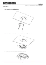
Wall Mounting 


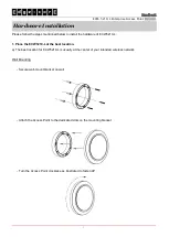
- Secure wall-mount bracket on wall 


- Attach the Access Point to the dedicated slots on the mounting bracket 


- Turn the Access Point clockwise as illustrated to fasten AP 


Summary of Contents for ECW5210-L

Page 1: ...ECW5210 L Enterprise Access Point Handbook ...

Page 2: ...Consult the dealer or an experienced radio TV technician for help Any changes or modifications not expressly approved by the party responsible for compliance could void the user s authority to operate this equipment This device complies with Part 15 of the FCC Rules Operation is subject to the following two conditions 1 This device may not cause harmful interference and 2 this device must accept a...

Page 3: ...1000 4 11 Safety EN 60950 1 A11 Caution This declaration is only valid for configurations combinations of software firmware and hardware provided and supported by Edgecore Networks Corporation The use of software or firmware not provided and supported by Edgecore Networks Corporation may result in the equipment no longer being compliant with the regulatory requirements European standards dictate m...

Page 4: ...nt wireless links to form wider wireless network coverage ECW5210 L also features multiple ESSIDs with VLAN tags and multiple Virtual APs great for enterprise applications such as separating traffic from different departments using different ESSIDs The PoE Uplink port is able to receive power from Power over Ethernet PoE sourcing devices This Handbook provides instructions and reference materials ...

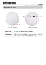
Page 5: ...anel ECW5210 L s Rear Panel 1 LED Indicators An LED indicator is available to show the uplink status 2 12V 2 5 A Attach power adaptor here 3 Uplink PoE Port Offers uplink connection This port can be used to connect to a controller gateway or directly to the Internet 802 3at PoE is also supported ...

Page 6: ...rdware of ECW5210 L 1 Place the ECW5210 L at the best location a The best location for ECW5210 L is usually at the center of your intended wireless network Wall Mounting Secure wall mount bracket on wall Attach the Access Point to the dedicated slots on the mounting bracket Turn the Access Point clockwise as illustrated to fasten AP ...

Page 7: ...L Enterprise Access Point ENGLISH 3 Ceiling Mount Secure ceiling mount bracket on ceiling Attach the Access Point to the dedicated slots on the mounting bracket Turn the Access Point clockwise as illustrated to fasten AP ...
Page 8: ...power over to ECW5210 L ECW5210 L Uplink port is capable of receiving DC currents Connect an IEEE 802 3at compliant PSE device e g a PoE switch to the Uplink port of ECW5210 L with the Ethernet cable Connect a 12V 2 5A adaptor optional to the DC power jack If needed use the DC extension plug included Now the Hardware Installation is complete Using a different power adapter may damage this system T...

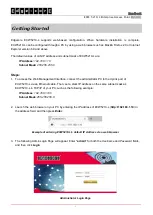
Page 9: ...ss the Web Management Interface connect the administrator PC to the Uplink port of ECW5210 L via an Ethernet cable Then set a static IP address on the same subnet mask as ECW5210 L in TCP IP of your PC such as the following example IP Address 192 168 1 100 Subnet Mask 255 255 255 0 2 Launch the web browser on your PC by entering the IP address of ECW5210 L http 192 168 1 10 in the address field an...

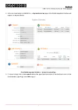
Page 10: ... L a System Overview page of the Web Management Interface will appear as depicted below The Web Management Interface System Overview Page 5 To logout simply click on the Logout button at the upper right hand corner of the interface to return to the Administrator Login Page Click OK to logout ...

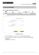
Page 11: ...p 1 Change Administrator s Password Change Password Page Click on the Utilities icon on the main menu and select the Change Password tab Enter a new password with a length of up to 32 characters and retype it in the Re enter New Password field Click SAVE to save the changes ...

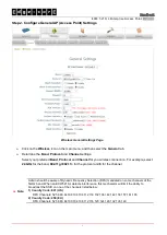
Page 12: ...ection For example select 2 4GHz for the band 802 11g 802 11n for the protocol and 6 for the channel Note Admin should be aware of Dynamic Frequency Selection DFS mandated on some channels of the 5GHz band When an ECW5210 L detects interference this mechanism will limit the ability to broadcast the SSID on one of the channels listed below 1 Country Code 841 US DFS Channels 52 56 60 64 100 104 108 ...

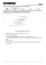
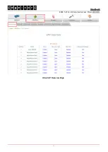
Page 13: ... 16 virtual APs VAPs per RF Card Configure VAP profile settings a Select the VAP Configuration tab to configure the settings of the desired VAP b Enable a specific VAP from the drop down menu of Profile Name and configure related settings below Check VAP status After finishing VAP configuration the status of enabled Virtual APs shall be reflected on the VAP Overview page ...

Page 14: ...Handbook ECW 5210 L Enterprise Access Point ENGLISH 10 Virtual AP Overview Page ...

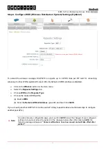
Page 15: ...ter Settings tab Choose WDS as the Repeater Type Choose the desired WDS profile a Enable WDS b Enter the Remote AP MAC Address peer AP and then Click SAVE If you are using another ECW5210 L as the peer AP simply repeat the above mentioned steps to configure another peer AP s Note On each and every configuration page you may click SAVE to save the changes of your configured settings but you must re...

Page 16: ...After ECW5210 L s network configuration is completed please remember to change the IP Address of your PC Connection Properties back to its original settings in order to ensure that your PC functions properly in its real network environments It is strongly recommended to make a backup copy of your configuration settings P N V34220171018 ...

Reviews: