


PPS20
–
User Manual Rev. 1.10
EDFelectronics JRMM Sp. z o.o. sp.k.
Rybnicka 64, Radlin 44-310, Poland
; e-mail: [email protected] tel.: +48 604 343 504
33
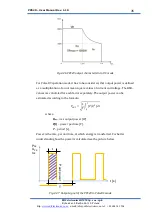
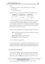
Where:
P
RMS
–
RMS (Root Mean Square) output power [W]
U
Pk
–
peak output voltage [V],
I
RMS
–
RMS (Root Mean Square) output current [A],
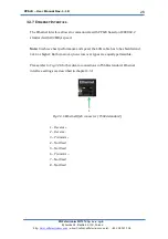
For more details, please refer to the chapter 4.2.4
4.2.2.
HV
O
UTPUT
S
ELECTION
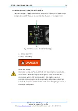
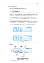
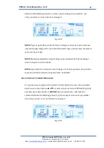
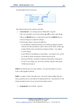
PPS20 can run with 2 outputs. They are not working parallel
–
only one can be
selected at the time. Current output selections is displayed on the main menu
–
Fig4.2.4
Fig. 4.2.4
NOTE:
There is possible to assign any name to the output if preferred
–
according
to used target for example. For customized naming please refer to the chapter
4.3.3
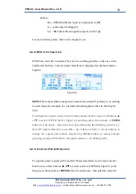
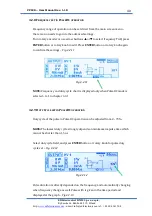
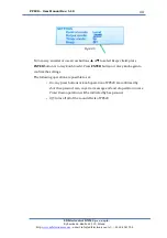
To change the output selection, turn rotary encoder knob or use arrow buttons
▲
or
▼
to select
OUTPUT
field (
Fig.4.2.4
) and then press the encoder or
ENTER
button to edit mode
–
this will turn selected field into the blinking ( about 1/s ).
Now HV output selection is possible
–
use rotary encoder or arrow buttons to
change the output and confirm selection by ENTER button or rotary encoder
pressing; system will return to the option selection
–
no blinking tabs.
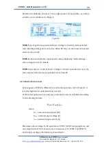
4.2.3.
C
ONSTANT
P
OWER
O
PERATION
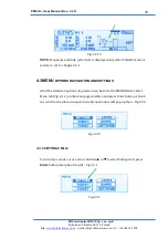
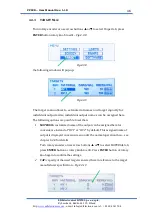
To operate power supply with Constant Power Operation, turn rotary encoder
knob or use arrow buttons
▲
or
▼
to select power in
SET
field (
Fig.4.2.5
) and
then press the encoder or
ENTER
button to edit mode
–
this will turn selected