background image

| 13


Field Report

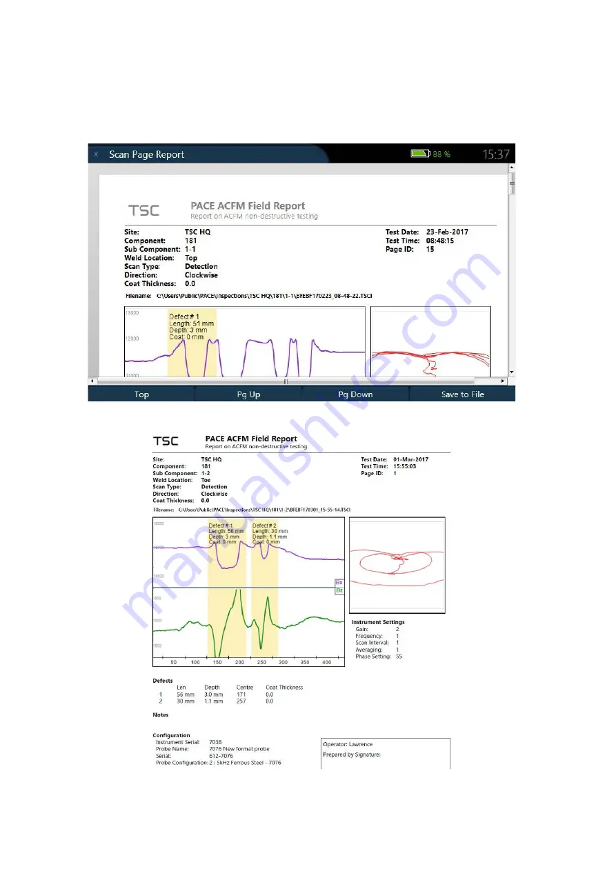
The field report function allows the operator to collect all the scan information (defect info, notes, 
probe info, photos) and creates a formatted report in pdf and word format. Navigate to 

F4

 button 

More

” and select “

Create/Edit Scan Report

”.

Figure 17 

Field Report Generation

Figure 18 

Example Field Report

Pressing the 

F4

 button “

Save to File”

 will save the report to the hard drive. If the page information 

is subsequently edited, recreating and then saving the report will update the information. Additional 
images of the scan (zoomed in, different scale etc.) can be added to the report using the “

Add 

Chart Image to Report

” function.

Data Analysis

Summary of Contents for TSC PACE

Page 1: ...TSC PACE Getting Started with...

Page 2: ...eplay 9 Camera 10 Defect Sizing 11 Field Report 13 Page Properties 14 System Settings 15 System Settings 15 Data Backup 16 Clearing Scan Pages and Information 16 Restoring Lost Data 16 Software Update...

Page 3: ...ven track record in the oil and gas industry ACFM is an electromagnetic technique that uses a probe to induce a small uniform AC current to flow in the surface of the material under test Defects in th...

Page 4: ...nd unpause the data collection during a scan 4 F1 F4 Page specific function buttons 5 Question mark Used to open context specific help files 6 Yellow arrows Used for selection during navigation and fo...

Page 5: ...are information namely the PACE instrument serial number SENSU probe serial number and the next recalibration date The bottom right hand side displays the next scan parameters and can be altered in th...

Page 6: ...levant to the inspection before the job begins Figure 4 Job Setup Window In this window the operator can add edit the Operator names Site Component and Sub Component used for the job s The operator ca...

Page 7: ...edit a copy of one the entries as a new entry Select allows the operator to select an entry and goes back to the previous screen Edit opens a new window that allows the operator to edit the entry move...

Page 8: ...ducted through insulating coating the thickness of the coating can be specified here The clock marks settings located in the bottom right of the screen can be configured to give the desired start and...

Page 9: ...be viewed in the info box under the butterfly plot Config mode is the default modes and takes its scale numbers directly from the probe file Centered mode is a dynamic scanning mode that tracks the B...

Page 10: ...options before pressing Start scan button to begin the scan Figure 8 Next Scan Parameters Quick Access Markers During the scan the operator can add marks to the data by pressing A C or T for linear m...

Page 11: ...t Scroll and Zoom The Scroll and Zoom screen is where the operator can zoom and move the selected screen Figure 10 The Zoom Function The operator can zoom in and out using F1 and F2 function buttons a...

Page 12: ...ws the operator to take photos of the inspection piece to be included in the report or imported separately Figure 12 Camera Pictures can be taken using the F4 button Take Picture or the T button The n...

Page 13: ...ndow is moved using the left right arrows and the width of the window is adjusted using the up and down arrow Figure 14 Defect Sizing Manual Snapping In manual snapping mode the Bx and Bz sizing lines...

Page 14: ...gion with defect information F4 button will save the calculated length and depth This is displayed on the scan page as a defect region with text displaying the defect length depth and coating thicknes...

Page 15: ...t Create Edit Scan Report Figure 17 Field Report Generation Figure 18 Example Field Report Pressing the F4 button Save to File will save the report to the hard drive If the page information is subsequ...

Page 16: ...w the full scan parameters from the Page Properties window Pressing the F4 button More then Page Properties will open the window Figure 19 Page Properties From the parameter list operator name scan di...

Page 17: ...s from 3 10 minutes The brightness setting dims and brightness the screen to the operators preference this can also be done in the home screen using the up down arrows The timezone setting changes the...

Page 18: ...ble to delete the scan pages and job setup information from the system From the system settings menu pressing the F2 button Clean Scan pages and F3 button Clean User data will delete the scan pages an...

Page 19: ...he USB stick with the PACE software inserted pressing the F4 button More then Update Software will initiate the installation process Figure 22 PACE Software Update Note that a software update will del...

Page 20: ...e instrument gets too hot a waning message will display informing the operator that the instrument will auto shutdown in 1 minute It is recommended the user stops scanning and save the data before the...

Page 21: ...ndle a damaged or leaking battery with extreme care If you come in contact with electrolyte wash the exposed area with soap and water If it contacts the eye flush the eye with water for 15 minutes and...

Page 22: ...clean your Instrument disconnect the Instrument from the electrical outlet and remove any installed batteries Clean your Instrument with a soft cloth dampened with water Do not use liquid or aerosol...

Page 23: ...21...

Page 24: ...Nodescanner Pace Sensu TSC and their associated logos are trademarks or registered trademarks of Technical Software Consultants Ltd wholly owned subsidiary of Eddyfi NDT Inc in the United Kingdom and...

Reviews: