ECUMASTER ADU-5/ADU-7
User Manual
(08/22/2018, version 1.0.101)
Page 1: ...ECUMASTER ADU 5 ADU 7 User Manual 08 22 2018 version 1 0 101...
Page 2: ...B Flash drive pen drive 25 Low side outputs 25 Windows software 26 Pages 36 Creating a page 36 Page elements 38 Adding page elements 40 Page switching 48 Startup screen 50 Objects 51 Gauge 51 Classic...
Page 3: ...99 Timers 99 Tables lookup tables 100 Switches virtual switches counters 102 Numbers mathematical channels 103 5 Functions 106 Alarms 111 User Lights 113 Logging channels 114 Logging to USB memory 116...
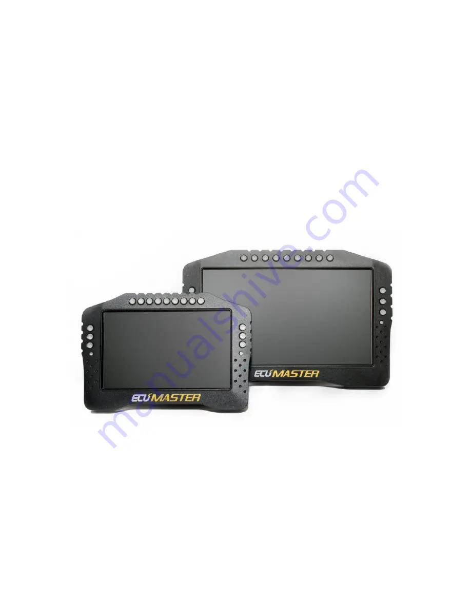
Page 4: ...mfort in various lighting conditions a high quality LCD display was chosen with a brightness of 600 cd m2 for the ADU5 display and 1000 cd m2 for the ADU7 display In order to reduce reflections the di...
Page 5: ...re controlled input sensitivity VR Hall software controlled 4K7 pull up resistors used for engine speed sensors Flex Fuel wheel speeds turbocharger shaft speed All digital inputs can be used as a swit...
Page 6: ...Technical drawing ADU 5 Drawing all dimensions in mm Page 6 137...
Page 7: ...ADU 7 Drawing all dimensions in mm Page 7 137...
Page 8: ...n with PC Flashes green when online Light sensor Light sensor is used for automatic control of the display and light emitting diodes brightness User led 1 6 RGB LEDs that can be controlled by user fun...
Page 9: ...nd will be difficult to install or remove The portion of the crimp that supports the insulation must be circular and of a diameter equal to or smaller than the terminal In order to insert or remove te...
Page 10: ...ked position If excessive resistance is encountered check to ensure that no terminals are inserted too far forward In order to remove a terminal move the red terminal lock to the halfway position as d...
Page 11: ...7 RS232 RXD RXD receiving signal for RS232 serial communication Used for connection to EMU Classic Hondata Autronic SM4 and AIM compatible ECUs 8 RS232 TXD TDX signal transmitting for serial RS232 9...
Page 12: ...input 2 The only input that can be used by a Flex fuel sensor 22 Power ground Device ground used by the AUX outputs and LEDs 23 Ground Device ground 24 Analog in 8 Analogue input 8 Measuring range 0 5...
Page 13: ...nable communication between PC and ADU Ecumaster USBtoCAN www ecumaster com Peak Systems PCAN USB www peak system com Kvaser USBcan www kvaser com All of these interfaces are equipped with DB9 connect...
Page 14: ...ity to interference is very high In a modern car there may be dozens of different electronic modules communicating with the use of the CAN bus The ADU device has two CAN buses the CAN1 bus is used for...
Page 15: ...pe the identifier may be 11 bits 0x0 0x7ff or 29 bit 0x0 0x1fffffff The number of data bytes may range from 0 to 8 ID DLC Byte 0 Byte 1 Byte 2 Byte 3 Byte 4 Byte 5 Byte 6 Byte 7 Below is a sample CAN...
Page 16: ...ADU supports the following serial formats AIM Ecumaster serial protocol Autronic SM4 and Hondata serial protocol For additional information go to the Serial communication section In the case of facto...
Page 17: ...ermination For more information see the CAN BUS section If the CAN bus speed is different than 1Mbps or if you want to isolate the ECU from the ADU CAN1 bus please use the CAN2 bus Detailed informatio...
Page 18: ...communication please use a shielded cable The diagram below shows an example of the connection Detailed information on connecting specific ECU brands to ADU can be found in the application notes at w...
Page 19: ...d by OBD2 at 100Hz and when the RPM channel is selected it will be refreshed 66 times per second 66Hz If you select an additional channel e g Throttle position the refresh rate for both channels will...
Page 20: ...DU In the CAN bus Serial setup options select the CAN bus that the GPS module is connected to GPS CANBus The GPS module s channels are listed in the channel list beginning with gps When using the GPS...
Page 21: ...abled error of the inertial sensors they are not taken into account when determining the vehicle s position gps speed Speed of the vehicle in km h gps headingMotion Direction of the vehicle motion Whe...
Page 22: ...to a system that includes a PMU it is recommended to connect CAN1 of the PMU with the CAN1 bus of the ADu This allows for easy communication with a PC and between the devices A sample connection diag...
Page 23: ...l effect sensors or optical sensors The digital inputs have built in switchable 2k2 pull up resistors pull up to 5V which may be used for Hall sensors or switches shorted to ground Magnetoresistive AB...
Page 24: ...ors such as pressure sensors oil fuel water etc or thermistors e g oil temperature sensor fuel level sensor These inputs can also used to connect switches The voltage of all analogue inputs may be tra...
Page 25: ...ng see the Logging section It is recommended to use name brand flash memory sticks compatible with USB 3 0 e g Sony USM8W3 USM16W3 USM32W3 Using USB flash drives with poor specifications can lead to d...
Page 26: ...installing and opening the software you should see the following screen The primary window is the Project tree 1 pane Use this pane to define all project items Click Add to add a new item You may cho...
Page 27: ...fixed values Page a single page displaying data If more pages are added they can be switched on and off or cycled through using conditional functions warning page when a temperature or pressure value...
Page 28: ...roject shown below The page preview screen 2 allows you to preview and edit the currently selected page If your PC is connected to the ADU all changes to a page are sent to the device in real time Pag...
Page 29: ...CAN to USB interface type The following interface types are supported USBtoCAN an interface by ECUMASTER PCAN USB a interface by Peak System Kvaser an interface by Kvaser CAN 1 status The status of th...
Page 30: ...llowing menu will on a tab New desktop Create new desktop The new desktop will appear on the far right Duplicate Duplicate a desktop This option creates a new desktop copying the contents of the origi...
Page 31: ...and select Close Pane from the drop down menu There are different pane types Configuration panes contain settings Another pane types are used for viewing data in real time such as the Variables inspec...
Page 32: ...e log pane has tabs that are used for displaying different log channel groups e g engine track etc These tabs work exactly the same way as the main desktop tabs To alter settings for a logged channel...
Page 33: ...out Left mouse button Click and drag to select an area Middle mouse button Move the log area When changing or adding a channel a channel selection pane appears on the graph In order to search enter th...
Page 34: ...figurations to a selected file This allows to transfer configurations between computers Save desktop templates Saves desktop configurations to a selected file This allows to transfer configurations be...
Page 35: ...r dialogue Displays a dialogue for managing the dashboard textures graphics You will find more information regarding texture management further in the manual Customize keys Changing the shortcut keys...
Page 36: ...page which can be overlaid on another page Overlay with background a page similar to the Overlay page but with a non transparent background Additionally an alert or warning can be displayed regardless...
Page 37: ...e channel or function that can automatically activate the page Background style Solid color the background is a solid color defined by the Background Color field Theme the background is a predefined g...
Page 38: ...ext Displays text in different font sizes and colours You can also attach a log channel e g injection time cooling liquid temperature etc to the text Time Displays formatted time You can choose from t...
Page 39: ...thermal imaging cameras and indicates their maximum temperature This indicator can also display tire temperature in the form of horizontal bars with a temperature gradient 16 values for each tire Trac...
Page 40: ...ge editor After entering the parameters shown below the page will look as follows Now we will add the current lap time To do this a Time item should be added We will use a Text item to visually repres...
Page 41: ...e Position X and Position Y fields Related items are best organized using the Grouping function This allows you to organize several functions and move them as a single group You can also automatically...
Page 42: ...g liquid temperature etc and this data is represented in the ADU software by the ecu channels After loading the proper CANX file for the connected computer or configuring the serial connection the ecu...
Page 43: ...Values with some degree of instability e g oil or fuel pressure pulsation are very difficult to read as they change rapidly Limiting the update frequency acts as a filter Measurement units are configu...
Page 44: ...emp png icon the indicator will look like the example below Next we will copy the created indicator twice in order to create a fuel level and oil pressure indicator After copying set their new positio...
Page 45: ...ion and set Scale to 900 Note that our texture is displayed over the existing elements To move it underneath we should rearrange it as the first element on the page The order of application of element...
Page 46: ...indicator to show values of channels and variables Enter the name of a channel or variable in the Channel field In addition to the current value of the channel the measurement unit may also be display...
Page 47: ...to the page using an Image indicator The indicator color may be assigned to a channel or function We set red as the default colour GPS not working changing to green when GPS is functioning properly We...
Page 48: ...ce two text fields over and under the icon The upper field will indicate the number of satellites gps numSatelites channel while the lower field will display the current GPS module status For the gps...
Page 49: ...a CAN bus The button to be used for switching between the pages must be defined in the Buttons panel The following example shows how to connect and configure a page switching button The button is conn...
Page 50: ...The main use for this type of switching is Overlays They allow the application of an overlay of another page on the currently displayed page whenever an event occurs To do this a function that will a...
Page 51: ...Color The colour of the displayed texture Background color The colour of the background Page 51 137...
Page 52: ...layed for the Value and Legend parameters Min Max The minimum and maximum value displayed by the indicator Display value This option allows you to show or hide the displayed Value parameter Update fre...
Page 53: ...indicator colour when its value differs from 0 The alarm colour is defined in the Alarm Color field Radius The indicator diameter in pixels Line width The indicator line width in pixels Decimal value...
Page 54: ...ndicator Display value This parameter allows you to hide the Value displayed in the gauge center Update frequency The update frequency on the Value parameter screen The screen is updated 50 times per...
Page 55: ...tive value and marker in the form of a section will be displayed Num subticks This value defines the number of divisions between the main markers Indicator width The width of the hand showing the curr...
Page 56: ...when the Value parameter is greater than the Redline start value When value below display the bar in Redline color when the Value parameter is lower than the Redline start value Redline start This par...
Page 57: ...de the Value displayed Update frequency The update frequency on the Value para meter screen The screen is updated 50 times per second 50Hz Quickly changing variables are very difficult to read at this...
Page 58: ...for tick This value defines the number of decimal places drawn for the indicator description Color The indicator frame colour Background color The indicator background colour Bar color The indicator...
Page 59: ...line start value When value below displays the bar in Redline color when the Value parameter is lower than Redline start Redline start This parameter defines the value for a condition defined by the R...
Page 60: ...in pixels Border width The width of the line surrounding the indicator in pixels Background color default Inactive indicator background colour Background color active Active indicator background colou...
Page 61: ...Displays channel value in separate line Second line font Font size for secont text line Text A field containing the displayed text Text width The area width used by the Text align functions For exampl...
Page 62: ...Value parameter Unit Selection of a unit for displaying a value e g kPa Bar Psi You can define your own unit in the Custom unit field To do this select User in the Unit field Custom unit This field i...
Page 63: ...select the Devices Set real time clock from the application menu Current lap the current lap time Last lap the last lap time Best lap the best lap time Session time an internal clock measuring the cur...
Page 64: ...in the Scale parameter 400 in order to quadruplicate it etc Scale This parameter determines the scale of a texture or the number of its copies for the Tile modes Mirror X Y It allows you to mirror im...
Page 65: ...d Color redline When using the Classic bar this determines the colour of the indicator bar above the Redline start value Redline start A value specifying the beginning of the engine speed limit area M...
Page 66: ...for the reverse gear 0 for the neutral gear 1 for the first gear etc respectively Parameter Description Position X Y Object position on the page The reference point is the upper left corner of a rect...
Page 67: ...ccelerometer requires calibration after installing the device Parameter Description Position X Y Object position on the page The reference point is the upper left corner of a rectangle around the obje...
Page 68: ...ion X Y Object position on the page The reference point is the upper left corner of a rectangle around the object Width Object width Height Object height Gain color The colour of the graph when the cu...
Page 69: ...round the object Style Tires temperature displayed as tires Bar temperature displayed as gradients Width Object width available only for the Bar style Height Object height available only for the Bar s...
Page 70: ...range of the cameras is in the ADU Configuration Tire temperature cameras panel Parameter Description Position X Y Object position on the page The reference point is the upper left corner of a rectan...
Page 71: ...oint is the upper left corner of a rectangle around the object First column bkgrd color The first column background colour First column Text color The first column text colour Table bkgrd color 1 The...
Page 72: ...nce point is the upper left corner Rectangle type The type rectangle displayed Border displays only the rectangle frame Border fill displays the frame and its filling fill Only fill displays only the...
Page 73: ...left corner of a rectangle around the object Color The line colour Width The line width the distance between the beginning and the end of the line along the X axis Height The line height the distance...
Page 74: ...e point is the upper left corner of an rectangle around the object Circle type The type of circle displayed Border displays only the rectangle frame Border fill displays the frame and its fill fill On...
Page 75: ...d custom texture or Add custom icon After selecting a file with a graphics png jpg and bmp formats are supported a dialogue will be displayed that will enable you configure the texture Parameter Descr...
Page 76: ...an alpha channel The texture is quantized to 256 unique colours This format is suitable for coloured textures e g a company logo It uses little memory however it displays a low rendering efficiency an...
Page 77: ...tary switch The number of the positions of the rotary switch is defined as Min value Max value Linear analog sensor this type of input is used for measuring voltage you select Voltage as a Unit or any...
Page 78: ...Min value for voltage This value defines the minimum sensor value for the defined Voltage when using a Linear analog sensor Max value for voltage This value defines the maximum sensor value for the d...
Page 79: ...pressing the Wizard button a dialog window will pop up allowing you to define a sensor using 3 temperature values and the corresponding sensor resistance You may select a calibration for common senso...
Page 80: ...in the particular cells To change the table size right click on it and select one of the Modify bins options You can preview the analogue input values in the Analog monitor panel showing a channel val...
Page 81: ...sensor in order to measure the vehicle engine speed Only D1 input can be used to measure the engine speed Flex Fuel a digital input used for reading the content of ethanol in fuel and the fuel temper...
Page 82: ...This allows for the calibration of values such as turbocharger speed or vehicle speed Timeout Time to reset freqency if there is no incoming signal pulse Example configurations Engine speed RPM read o...
Page 83: ...ation of a wheel speed read out from an ABS sensor connected to Digital Input 4 The d_absFrontRSpeed variable value equals the input frequency multiplied by 10 and divided by 32 multiplier divider Pag...
Page 84: ...the output is active connected to ground Analogue output The analogue output control channel is available in the Outputs panel as AOut channel It should be assigned a variable representing a value in...
Page 85: ...The value of the t_conversionTable should be assigned to the AOut channel field in the Outputs panel Page 85 137...
Page 86: ...d for each LED On Off the simplest control where an LED assumes two states off if the value of the variable assigned in the Channel field equals 0 or on if the value of the variable in the Channel fie...
Page 87: ...Channel field equals zero Color 2 When using the Choose and Choose override type it defines the colour when the variable in the Channel field differs from zero Channel 3 A variable defining the third...
Page 88: ...n define up to 5 tracks of your own If the track area coincides with a track area defined in the device the one defined by the user will have the priority Parameter Description Enable Enables a given...
Page 89: ...Page 89 137...
Page 90: ...evel 2 Source channel A channel variable determining the amount of fuel in the tank Usually a 2D table with calibration is used for this purpose Maximum step change The maximum allowed fuel level chan...
Page 91: ...log as ecu tps Timing advance The ignition timing angle Shown in the log as ecu ignAngle Fuel pressure The fuel pressure Shown in the log as ecu fuelPress Engine coolant temperature The engine coolant...
Page 92: ...value of 0 means an inactive output a value of 1 means an output connected to ground Aux2 channel A channel variable controlling the AUX 2 output A value of 0 means an inactive output a value of 1 me...
Page 93: ...th the OK button the selected channels will be added to the Project Tree In addition one or more CANbus Massage Objects responsible for receiving frame groups will be created Custom CAN streams CANbus...
Page 94: ...must be divisible by Size without a remainder For example you can receive 8 frames from the range of 0x600 607 using one mob However it is not permitted to receive frames from the range of 0x601 608 u...
Page 95: ...s doesn t have to be divisible by the Size This results from the fact that the communication takes place using only one CAN ID Compound frames are characterized by containing an index on the first 4 8...
Page 96: ...the used Message object 3 The next step is setting the Byte offset parameter It marks the location of our values in the CAN frame 0 7 You should select the interpretation of the number signed unsigned...
Page 97: ...6 Choosing a default value A default value is used from starting the device until receiving the first frame containing the channel IMPORTANT You should take into account decimal places in this consta...
Page 98: ...s limited to a range of 128 127 and sent as a single byte in a frame 16bit big endian the value is sent with the most significant byte first and least significant byte second for example the value 0x1...
Page 99: ...e will be sent 15 decimal Below is a frame preview as seen in the ECUMASTER Light Client application At the A1 analogue input the voltage is exactly 5V Channel 0 Channel 5 respectively as in the above...
Page 100: ...onds Timers are started by means of a channel defined by Start Channel and an edge defined by Start edge Rising or Falling Similarly Timers are stopped by means of a channel defined by Stop Channel an...
Page 101: ...e two dimensional leave the Axis Y channel empty You should also define the axis scope min and max To change the number of elements in a table change the step parameter which defines the step Table si...
Page 102: ...t combines two commands first the horizontal and then vertical interpolation Equalize selection E Smoothing out the selected cells Insert row above Alt Ctrl Up Inserting a row above the selected cell...
Page 103: ...g the First state and Last state parameters as well as the default value by means of the Default state parameter This element will operate as a counter After each appearance of aTrigger edge in the In...
Page 104: ...1 10 100 or 1000 the fraction remainder is rejected You may also choose to use the raw value with no modification Raw applies to the voltage from analogue inputs for example where it is a value from...
Page 105: ...Indirect calculations are performed using a broader range of numbers app 2 109 For example calculations can be performed for the following values 1000 1000 123 In the end the result is limited clampe...
Page 106: ...alue 2 if Value_1 Value_2 then FACTOR Value_1 else FACTOR Value_2 Max Value 1 Value 2 if Value_1 Value_2 then FACTOR Value_1 else FACTOR Value_2 Clamp Input Min Max if Input Min then FACTOR Min else i...
Page 107: ...ctive the a_autoActiveSw switch is on when manual lighting mode is active the a_forceActiveSw switch is on Both switches are connected to analogue inputs of the device An analogy comparing a logic fun...
Page 108: ...lectronics this operation represented by the NOT gate Comparing operations Equal Returns 1 when the Channel value Constant returns 0 otherwise Not Equal Returns 1 when the Channel value Constant retur...
Page 109: ...nal signal Next it is shown how the setting of the Delay true and Delay false parameters affects this signal The bulb goes on following a button press and remains on for another 120 s after releasing...
Page 110: ...ations Toggle Changes the state between 0 and 1 each time a selected edge appears in the Channel Rising or Falling The initial value of this operation at device startup may be defined by means of the...
Page 111: ...ion will be the previous value b For the Polarity Below parameter If the value of the Source channel is lower than the predefined Lower value threshold the value of the operation will be 1 If it is gr...
Page 112: ...ameter The alarm text may also show the current channel value Use a pound sign to show a value If you wish to display the pound sign enter two symbols 2 Qualifier You can additionally enter a precondi...
Page 113: ...on of the Configuration pane you can define one or two alternative buttons for acknowledging an alarm 5 Global settings There may be a situation when two alarms appear simultaneously Such situation ca...
Page 114: ...l affect its colour as well as which colour will be shown Operation name Parameters Description On Off Channel Color2 When the Channel value is true non zero the diode has the colour as defined by Col...
Page 115: ...four available 5 The logging bandwidth budget used expressed in for particular Log conditions 6 The logging bandwidth budget used expressed in bytes 7 Logging configuration may be performed using a po...
Page 116: ...ion takes place 25 times per second If the values of two channels are true non zero e g the one selected in the Log Cond2 channel field and the one selected in the Log Cond3 channel field the first on...
Page 117: ...n Blue USB memory is not connected to the ADU device Green USB memory is detected and the file system information is being loaded This state usually lasts a few seconds Green Log file saving in progre...
Page 118: ...ry should be removed from the port connected to the ADU and connected to a PC After connecting a USB memory stick to a PC choose the Receive logs command from the Devices menu Shift F4 in the ADU clie...
Page 119: ...n be reset by means of a button defined in the Buttons panel Reset distance meter channel trigger Engine hour meter adu engineHours It measures the number of hours the engine has run ecu rpm 0 channel...
Page 120: ...o set the actual vehicle mileage as the initial odometer mileage This is done by means of a command from the Tools Set meters menu To set a given meter check the Set selection field for the meter and...
Page 121: ...rs the min max values of the ECU channels are recorded in the non volatile memory of the device and remain in it even after the device is restarted However you can decide when the process of recording...
Page 122: ...activated by releasing a button Click a function is activated by quickly pressing and releasing a button Hold a function is activated by pressing and holding a button Position Description Next page Sw...
Page 123: ...um RPM at which all LEDs begin to blink red Neutral and reverse The RPM at which the first LED for the reverse and neutral gear lights up 1 to 8 The RPM at which the first LED for gears 1 to 8 lights...
Page 124: ...llowing map lights up individual LEDs between 6000 and 6400 RPM with a 50 RPM step When using the reverse and neutral gears the values for first gear are used Control by means of an external channel C...
Page 125: ...ll values range between 0 and 100 LCD brightness Autobrightness User led brightness Autobrightness User led master brightness Led brightness Shift light brightness Autobrightness Shift light master br...
Page 126: ...larms parameter is set in the Multiple alarm mode parameter Alarm height The height of the rectangle displayed as an alarm background Screen Rotate screen This allows you to rotate the screen 180 degr...
Page 127: ...will be displayed Color The colour of the displayed texture Background color The colour of the background Protection The Protection panel contains options related to the password protection of the de...
Page 128: ...conditions for the profiles are met Log Cond2 channel A channel function activating the logging of the Cond 2 profile Log Cond3 channel A channel function activating the logging of the Cond 3 profile...
Page 129: ...tween the Hondata computer and the ADU is to be used Hondata 115200 a serial protocol consistent with the Hondata PRO computer protocol speed of 115 kbps A signal inverter between the Hondata computer...
Page 130: ...registered by a receiver inside a car The receiver informs the ADU of the crossing of the start finish line In addition to measuring time the GPS module allows to display the anticipated lap time Pre...
Page 131: ...track you are currently on The list of automatically detected tracks is included in Appendix 1 If a track is not included in the list you can add a track of your own see the Panels User tracks chapte...
Page 132: ...w with a log files selection will appear To upload the desired log double click on it with the left button Then move on to the Track tab The Track Preview pane should display the entire track covered...
Page 133: ...tour will change too The Lateral g for corners parameter defines the lateral g force above which a given track part is interpreted as a turn The Min straight length parameter defines the minimum secti...
Page 134: ...n the segments table The selected section is automatically highlighted in the preview screen Press OK after you finish editing To save the track you created press the disk icon The last saved read ref...
Page 135: ...ine and in our example it was scored in laps 3 and 4 This time is the feasible time that you can score The channels that may be helpful in analysing data Channel Description adu track lap Displays the...
Page 136: ...Zolder Czech Republic Automotodrom Brno Itally Misano World Circuit Fanciacorta International Racalmuto Monza Latvia Bikernieki Netherlands Assen circuit Aspen circuit Zandvoort Poland Tor Pozna Tor...
Page 137: ...Document history Page 137 137...