background image


16 

Connecting Optional Devices 

WOL1/WOM1: Wake On LAN/Wake On Modem  

If you have installed a LAN card, use the cable provided with the card 
to plug into the mainboard WOL1 connector. This enables the Wake 
On LAN (WOL) feature. When your system is in a power-saving 
mode, any LAN signal automatically resumes the system. You must 
enable this item using the Power Management page of the Setup Util-
ity. 

Pin 

Signal Name  


5VSB 
Ground 
SENSE 

If you have installed a modem, use the cable provided with the modem 
to plug into the mainboard WOM1 connector. This enables the Wake 
On Modem (WOM) feature.  

When your system is in a power-saving mode, any modem signal 
automatically resumes the system. You must enable this item using the 
Power Management page of the Setup Utility. See Chapter 3 for more 
information. 

USB2: USB port 3, 4  

The mainboard has two USB ports installed on the rear edge I/O port 
array. However, some computer cases have a special module that 
mounts USB ports at the front of the case. If you have this kind of 
case, use auxiliary USB connectors USB2 and USB3 to connect the 
front-mounted ports to the mainboard. 

Pin 

Signal Name  

Pin 

Signal Name  


Port 3 power 
Port 3 USB- 
Port 3 USB+ 
Port 3 ground 
Protection key 


10 

Port 4 power 
Port 4 USB- 
Port 4 USB+ 
Port 4 ground 
Over current sensor 

Summary of Contents for P4ITA2

Page 1: ...evise and change this publication from time to time without the obligation of notifying any person of such revision or changes Trademarks IBM VGA and PS 2 are registered trademarks of Interna tional Business Machines Intel Pentium Pentium II and MMX are registered trade marks of Intel Corporation Microsoft MS DOS and Windows 95 98 NT 2000 are regis tered trademarks of Microsoft Corporation PC cill...

Page 2: ...e harmful interference to radio or television reception which can be determined by turning the equipment off and on the user is encouraged to try to correct the interference by one or more of the following measures Reorient or relocate the receiving antenna Increase the separation between the equipment and the receiver Connect the equipment onto an outlet on a circuit different from that to which ...

Page 3: ...sion Slots Installation 14 Connecting Optional Devices 16 Chapter 3 BIOS Setup Utility 18 Introduction 18 Running the SetupUtility 19 Standard CMOS Setup Page 20 Advanced Setup Page 21 Power Management Setup Page 23 PCI Plug and Play Setup Page 25 Load Optimal Settings 26 Load Best Performance Settings 26 Features Setup Page 27 CPU PnP Setup Page 28 Hardware Monitor Page 29 Exit 29 Chapter 4 Using...

Page 4: ...iv ...

Page 5: ...essors supporting front side bus FSB speeds up to 400 MHz and data bus bandwidths up to 3 2 GB s The P4ITA2 incorporates the Intel Tehama 850 Northbridge and Intel 82801BA ICH2 Southbridge chipsets combining support for dual channel RAMBUS DRAM RDRAM 2X 4X AGP 1 5V only and the AC 97 codec The Intel 82801I O controller hub includes an integrated audio codec controller that lets the processor effic...

Page 6: ...e system bus frequency Supports up to 2 GB of Rambus DRAM Supports a maximum memory bandwidth of 3 2 GB s AGP controller is AGP 2 0 compliant and supports 2x 4x Fast Write Protocol 1 5V only PCI IDE controller supports PCI bus mastering PIO modes 0 4 and UDMA 33 66 100 Two USB controllers double the bandwidth to 24 Mbps across four ports Integrated AC 97 audio that supports full surround sound wit...

Page 7: ...al Analog Converter resolution as well as 18 bit stereo full duplex codec with independent and variable sampling rates Expansion Options The mainboard comes with the following expansion options Five 32 bit PCI slots A 4xAGP slot AGP Pro slot optional A Communications Network Riser CNR slot Two IDE channels and a floppy disk drive interface The P4ITA2 supports Ultra DMA bus mastering with transfer ...

Page 8: ...re can also be used to set parameters for different proces sor clock speeds Bundled Software PC Cillin 2000 provides automatic virus protection under Windows 95 98 NT 2000 MediaRing Talk provides PC to PC or PC to Phone internet phone communication 3Deep delivers the precise imagery and displays accurate color in your monitor WinDVD2000 is a DVD playback application optional Dimensions ATX form fa...

Page 9: ...IDE drive ribbon cable and bracket q One auto install software support CD q Retention modules already mounted on the board q Two CPU retention brackets q Two dummy Rambus DRAM modules already inserted in RIMM slots Optional Accessories You can purchase the following optional accessories for this main board q Extended USB module q CNR v 90 56K Fax Modem card ...

Page 10: ...n t have a wrist strap discharge static electricity by touching the bare metal of the system chassis 3 Handle the mainboard carefully by the edges Avoid touching the components unless it is absolutely necessary During installation put the mainboard on top of the static protection packaging it came in with the component side facing up Pre Installation Inspection Inspect the mainboard for damage to ...

Page 11: ...l the mainboard in a system chassis case q Connect any extension brackets or cables to connecting headers on the mainboard q Install other devices and make the appropriate connections to the mainboard connecting headers Note 1 Before installing this mainboard make sure jumper JBAT1 is set to Normal setting See this chapter for information on locating JBAT1 and the setting options 2 Never connect p...

Page 12: ...8 Mainboard Components Note Any jumpers on your mainboard that do not appear in this il lustration are for testing only ...

Page 13: ... as mice or fax modems COM1 is identified by the sys tem as COM1 3 COM2 is identified by the system as COM2 4 5 Use the game port to connect a joystick or a MIDI de vice 6 Use the three audio ports to connect audio devices The left side jack is for a stereo line out signal The middle jack is for a stereo line in signal The right side jack is for a microphone Installing the Processor This mainboard...

Page 14: ...n 2 Identify the pin 1 corner on the CPU socket and the pin 1 corner on the processor 3 Match the pin 1 corners and insert the processor into the socket Do not use force 4 Swing the locking lever down and hook it under the latch on the edge of the socket 5 Apply thermal grease to the top of the CPU 6 Insert the CPU cooling fan heatsink assembly 7 Plug the CPU fan cable connector into the CPU cool ...

Page 15: ...RAM modules C RIMM must be inserted in un populated slots 1 Align the memory module with the slot The RIMM slots are keyed with notches and the RIMMs are keyed with cutouts so that they can only be installed correctly 2 Push the latches on each side of the RIMM slot down 3 Check that the cutouts on the RIMM module edge connector match the notches in the RIMM slot Cutouts Notches Latch Latch 4 Inst...

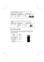
Page 16: ...you to clear the BIOS 1 Turn the system off 2 Remove all ATX power connectors 3 Short pins 2 and 3 on JBAT1 4 Return the jumper to the normal setting 5 Plug in all ATX power connectors 6 Turn the system on The BIOS is returned to the default settings Jumper Type Description Setting default JBAT1 3 pin Clear CMOS 1 2 Normal 2 3 Clear JBAT1 1 ...

Page 17: ...pe Description Setting default JP12 3 pin Enable on board audio codec 1 2 Enable 2 3 Disable JP12 1 The Panel Connector The panel connector provides a standard set of switch and LED con nectors usually found on ATX or micro ATX cases Refer to the table below for information Device Pins Empty 10 N C 9 Power ON OFF 6 8 Reset Switch 5 7 Green LED Indicator 2 4 HDD LED 1 3 HDD LED Pins 1 3 2 1 Reset S...

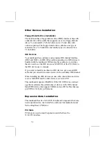
Page 18: ...d to set the IDE device as MASTER or SLAVE Refer to the IDE device user s manual If you want to install more than two IDE devices get a second IDE cable and you can add two more devices to the secondary IDE channel When installing two IDE devices on one cable ensure that one device is set to MASTER and the other device is set to SLAVE This mainboard supports UltraDMA 33 66 100 UDMA is a technol og...

Page 19: ... slot is used to insert CNR cards including LAN Modem and Audio functions 1 Remove a blanking plate from the system case corre sponding to the slot you are going to use 2 Install the edge connector of the add on card into the expansion slot Ensure that the edge connector is cor rectly seated in the slot 3 Secure the metal bracket of the card to the system case with a screw PCI1 PCI2 PCI3 PCI4 PCI5...

Page 20: ...s enables the Wake On Modem WOM feature When your system is in a power saving mode any modem signal automatically resumes the system You must enable this item using the Power Management page of the Setup Utility See Chapter 3 for more information USB2 USB port 3 4 The mainboard has two USB ports installed on the rear edge I O port array However some computer cases have a special module that mounts...

Page 21: ...rt Infrared ports allow the wireless exchange of information between your com puter and similarly equipped devices such as printers laptops Personal Digital Assistants PDAs and other computers Pin Signal Name Pin Signal Name 1 3 5 CIR receive 5V IR transmit 2 4 6 KEY Ground IR receiver ...

Page 22: ... coordination between system components If the Setup Utility configuration is incorrect it may cause the system to malfunction It can even stop your computer from booting properly If this happens you can use the clear CMOS jumper to clear the CMOS memory used to store the configuration information You can run the setup utility and manually make changes to the con figuration You might need to do th...

Page 23: ...sk type etc You can use the cursor arrow keys to highlight any of the options on the main menu page Press Enter to select the highlighted option To leave the setup utility press the Escape key To cycle through the Setup Utility s optional color schemes hold down the Shift key and press F2 Some of the options on the main menu page lead to tables of items with installed values In these pages use the...

Page 24: ...1901 2099 PU PD Modify Shift F2 Color F3 DetectAllHDD Date Time Use these items to set up system date and time Pri Master Pri Slave Sec Master Sec Slave Use these items to configure devices con nected to the Primary and Secondary IDE channels To configure an IDE hard disk drive choose Auto If the Auto setting fails to find a hard disk drive set it to User and then fill in the hard disk characteris...

Page 25: ...isabled ESC Quit SelectItem F1 Help PU PD Modify F5 Old Values Shift F2 Color F6 Load BIOS Defaults F7 Load Setup Defaults Quick Boot If you enable this item the system starts up more quickly be elimination some of the power on test routines 1st Boot Device 2nd Boot Device 3rd Boot Device Use these items to determine the device order the computer uses to look for an operating system to load at sta...

Page 26: ...you are booting the OS 2 operating system and you have more than 64MB of system memory installed L1 L2 Cache Leave these items enabled since all the processors that can be installed on this board have internal L1 L2 cache memory Cache Bus ECC This item can perform the error check cor rection function System BIOS Cacheable If you enable this item a segment of the system BIOS will be cached to main ...

Page 27: ...Old Values Shift F2 Color F6 Load BIOS Defaults F7 Load Setup Defaults Power Man agement Use this item to enable or disable a power management scheme If you enable power management you can use the items below to set the power management operation Both APM and ACPI are supported ACPI Aware O S This item supports ACPI Advanced Configu ration and Power management Interface Use this item to enable or ...

Page 28: ...rder to use this feature Use this item to do wake up action if inserting the PCI card Keyboard Power On Function If you enable this item you can turn the sys tem on and off by pressing hot keys on the keyboard You must enable the Keyboard Power On jumper and use an ATX power supply in order to use this feature Resume By Alarm The system can be turned off with a software command If you enable this ...

Page 29: ...or 98 Primary Graphics Adapter This item indicates if the primary graphics adapter uses the PCI or the AGP bus The de fault PCI setting still lets the onboard display work and allows the use of a second display card installed in a PCI slot Allocate IRQ for PCI VGA If this item is enabled an IRQ will be assigned to the PCI VGA graphics system You set this value to No to free up an IRQ VGA Frame Buf...

Page 30: ...up Page This page sets some of the parameters for peripheral devices con nected to the system AMIBIOS SETUP FEATURES SETUP C 2000 American Megatrends Inc All Rights Reserved OnBoard FDC Enabled OnBoard Serial Port1 3F8 COM1 OnBoard Serial Port2 2F8 COM2 Serial Port2 Mode Normal OnBoard Parallel Port 378 Parallel Port Mode Normal Parallel Port IRQ 7 Parallel Port DMA Channel N A AC97 Audio Controll...

Page 31: ... the onboard Primary and Secondary IDE channels Parallel Port IRQ Use this item to assign IRQ to the parallel port AC 97 Audio Controller This item enables or disables the AC 97 audio chip AC 97 Mo dem Controller This item enables or disables the AC 97 modem chip OnBoard MIDI Port Use this item to enable or disable the onboard MIDI port and to assign a port address MIDI Port IRQ Use this item to a...

Page 32: ...rends Inc All Rights Reserved CPU BRAND INTEL CPU Type Pentium 4 CPU Speed 1 7 GHz CPU Ratio 17 0x CPU Frequency 100 MHz CPU VCORE 1 680V ESC Quit SelectItem F1 Help PU PD Modify F5 Old Values Shift F2 Color F6 Load Optimal values F7 Load Best performance values CPU BRAND Type Core Volt age Ratio Frequency These items show the type core voltage ra tio and frequency of CPU installed in your system ...

Page 33: ... 5 292V 12 000V 11 890V 12 000V 11 856V ESC Quit SelectItem F1 Help PU PD Modify F5 Old Values Shift F2 Color F6 Load BIOS Defaults F7 Load Setup Defaults CPU System Temperature These items display CPU and system tem perature measurement FANs Volt age Measurements These items indicate cooling fan speeds in RPM and the various system voltage meas urements Exit Highlight this item and press Enter to...

Page 34: ...each software program and the location for your mainboard version More information on some programs is available in a README file located in the same directory as the software Note Never try to install software from a folder that is not specified for use with your mainboard Before installing any software always inspect the folder for files named README TXT INSTALL TXT or something similar These fi...

Page 35: ...Utility Folder Installation Notes later in this chapter The support software CD ROM disc loads automatically under Win dows 98 When you insert the CD ROM disc in the CD ROM drive the autorun feature will automatically bring up the install screen The screen has three buttons on it Setup Browse CD and Exit Note If the opening screen doesn t appear double click the file setup exe in the root director...

Page 36: ...ar This file may contain important information to help you install the software correctly Some software is installed in separate folders for different o perating systems such as DOS WIN NT or WIN98 95 Always go to the cor rect folder for the kind of OS you are using To install the software execute a file named SETUP EXE or IN STALL EXE by double clicking the file and then following the instruction...

Page 37: ...for the mainboard 1 Click Setup The installation program begins Mainboard ID Note The following screens are examples only The screens and driver lists will be different according to the mainboard you are installing The mainboard identification is located in the upper left hand corner ...

Page 38: ...mended 4 Click Next run the Installation Wizard An item installation screen appears 5 Follow the instructions on the screen to install the items Drivers and software are automatically installed in sequence Follow the onscreen instructions confirm commands and allow the computer to restart a few times to complete the installation ...

Page 39: ...ctory INTEL REALTEK CODEC then run SETUP EXE Installation for Windows NT4 0 1 Click Start 2 Click Settings and then click Control Panel 3 Double click the Multimedia icon 4 Select the Devices tab 5 Click Add 6 Select the item Unlisted or Updated Driver in the List of Drivers in the list box and then specify the path to the PCI audio NT drivers INTEL REALTEK CODEC NT4 7 Select Avance Logic Inc AC 9...

Page 40: ... inte grated on this mainboard Drivers are provided for Windows 2000 98 98SE ME 95 and Windows NT Installation for Windows 2000 98 98SE ME 95 To install the IDE drivers go to the directory INTEL INST then run SETUP EXE to install the IDE driver for your operat ing system ...

Page 41: ... a new BIOS that is incorrect your system will malfunction Refer to Chapter 3 Using BIOS for more information PC CILLIN The PC CILLIN software program provides anti virus protec tion for your system This program is available for Windows 2000 ME 98SE and Windows NT Be sure to check the r e adme txt and install the appropriate anti virus software for your operating system We strongly recommend users...

Page 42: ...stem that protects your Hard Disk Drive from virus intrusion accidental deletions and from system corruption To install the Recovery Genius software program run SETUP EXE from the following directory UTILITY RECOVERY GENIUS ENG RECOVERYGENIUS Language Genius The Language Genius is a software based product that helps you to learn new languages To install the Language Genius software program run SET...

Page 43: ...nDVD optional Go to the directory UTILITY WINDVD then run SETUP EXE to install the application software The WinDVD software is not free Before you install you need to register and get the serial number first ...

Reviews: