


97
Refrigerant may only be charged after
performed the vacuum drying process.
Always use gloves and glasses to protect
your hands and eyes during the charge
work.
Use electronic scale or fluid infusion
apparatus to weight refrigerant to be
recharged. Be sure to avoid extra
refrigerant charged, it may cause liquid
hammer of the compressor or protections.
Use supplementing flexible pipe to connect
refrigerant cylinder, pressure gauge and
outdoor unit. And The refrigerant should be
charged in liquid state. Before recharging,
The air in the flexible pipe and manifold
gauge should be exhausted.
After finished refrigerant recharge process,
check whether there is refrigerant leakage
at the connection joint part. (Using gas
leakage detector or soap water to detect).
13.8 Engineering of insulation
13.8.1 Insulation of refrigerant pipe
1
Operational procedure of refrigerant
pipe insulation
Cut the suitable pipe → insulation (except joint
section) → flare the pipe → piping layout and
connection→ vacuum drying → insulate the
joint parts
2
Purpose of refrigerant pipe insulation
During operation, temperature of gas pipe
and liquid pipe shall be over-heating or
over-cooling extremely. Therefore, it is
necessary to carry out insulation; otherwise
it shall debase the performance of unit and
burn compressor.
Gas pipe temperature is very low during
cooling. If insulation is not enough, it shall
form dew and cause leakage.
Temperature of gas pipe is very high
(generally 50-100
℃
) during heating.
Insulation work must be carried out to
prevent hurt by carelessness touching.
3
Insulation
material
selection
for
refrigerant pipe
The burning performance should over
120
℃
According to the local law to choose
insulation materials
The thickness of insulation layer shall be
above 10mm.If in hot or wet environment
place, the layer of insulation should be
thicker accordingly.
4
Installation highlights of insulation
construction
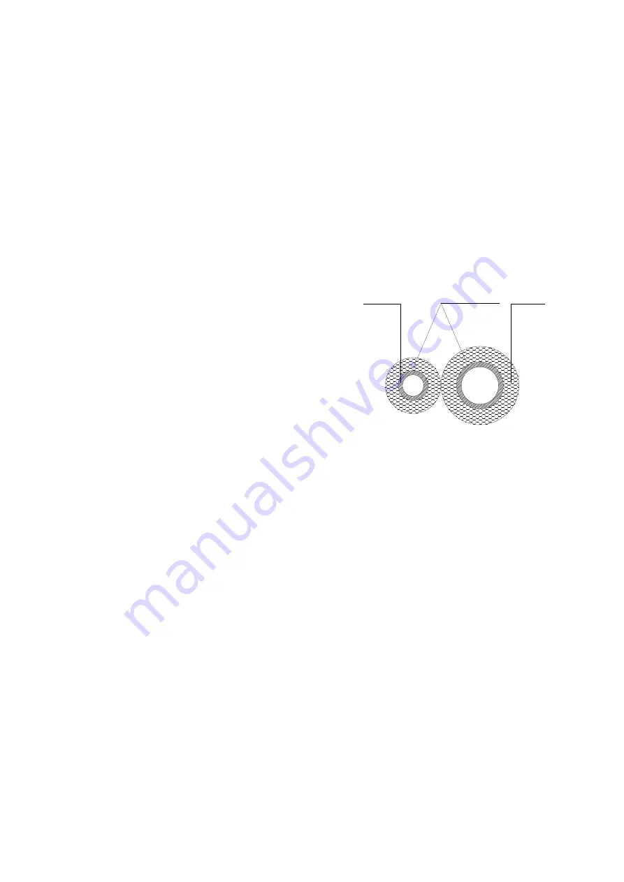
Gas pipe and liquid pipe shall be insulated
separately, if the gas pipe and liquid pipe
were insulated together; it will decrease the
performance of air conditioner.
L iq u id p ip e
I n s u la t io n m e te r ia l
G a s p ip e
The insulation material at the joint pipe
shall be 5~10cm longer than the gap of the
insulation material.
The insulation material at the joint pipe
shall be inserted into the gap of the insulation
material.
The insulation material at the joint pipe
shall be banded to the gap pipe and liquid pipe
tightly.
The linking part should be use glue to paste
together
Be sure not bind the insulation material
over-tight, it may extrude out the air in the
material to cause bad insulation and cause
easy aging of the material.
13.8.2 Insulation of drainage pipe
1
Operational procedure of refrigerant
pipe insulation
Select the suitable pipe → insulation (except
joint section) → piping layout and connection→
drainage test→ insulate the joint parts
2
Purpose of drainage pipe insulation
Summary of Contents for CTBU-09HWFN1-M(C)
Page 8: ...5 2 2 Part names of Indoor Outdoor units Cassette Units...
Page 9: ...6 A5 Duct Units A6 Duct Units...
Page 10: ...7 Console Units...
Page 11: ...8 Ceiling floor Units...
Page 12: ...9 HESP DUCT Units...
Page 21: ...18 2 3 4 7 Outside Water Pump for Optional When Ceiling Installation...
Page 29: ...26 Console Units 1 6 D ra in p ip e 1 9 5 H a n g in g a rm U n it m m 7 0 0 6 0 0 2 1 0...
Page 36: ...33 Console Units Ceiling floor Units...
Page 41: ...38 CFAU 09HRFN1 M C CFAU 12HRFN1 M C MCD 36HRFN1 M C MCD 48HRFN1 M D...
Page 42: ...39 CTBU 36HWFN1 M C CTBU 48HWFN1 M C...
Page 43: ...40 MUEU 18HRFN1 M C MUEU 24HRFN1 M C MUE 36HRFN1 M C...
Page 44: ...41 MUE 48HRFN1 M C MUE 60HRFN1 MW...
Page 45: ...42 MUE 36HRFN1 M C MUE 48HRFN1 M C...
Page 46: ...43 MUE 60HRFN1 MW MTIU 09HWFN1 M MTIU 12HWFN1 M MTIU 18HWFN1 M MTIU 24HWFN1 M...
Page 49: ...46 MOBA30 09HFN1 MT0W MOB30 12HFN1 MT0W...
Page 50: ...47 MOD30 24HFN1 MT0W MOD01 23HFN1 MT0W...
Page 51: ...48 MOD30U 36HFN1 M...
Page 57: ...54 CTBU 09HWFN1 M C Code 0 Code 1 Code 2 Code 3 Code 4...
Page 58: ...55 CTBU 12HWFN1 M C Code 0 Code 1 Code 2 Code 3 Code 4...
Page 59: ...56 CTBU 18HWFN1 M C Code 0 Code 1 Code 2 Code 3 Code 4...
Page 60: ...57 CTBU 24HWFN1 M C Code 0 Code 1 Code 2 Code 3 Code 4...
Page 61: ...58 CTB 36HWFN1 M C Code 0 Code 1 Code 2 Code 3 Code 4...
Page 62: ...59 CTB 48HWFN1 M C Code 0 Code 1 Code 2 Code 3 Code 4...
Page 78: ...75 12 Field Wiring 9K 24K 36K 48K 60K...
Page 79: ...76...
Page 129: ...126 P U P V...
Page 130: ...127 P W P N...
Page 147: ...144...
Page 193: ...190 5 Remove the four fixing screws of the fan motor then remove the motor 5...