


Operating the Limit Controller
50
UDC2500 Universal Digital Limit ControllerProduct Manual
8/05
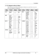
Diagnostic Error Messages
The
UDC
2500 performs background tests to verify data and memory integrity. If there is
a malfunction, an error message will be displayed. In the case of more than one
simultaneous malfunction, the messages will be displayed sequentially on the lower
display. If any of these error messages in Table 4-3 occur, refer to
Section 7 -
Troubleshooting
for information to correct the failure.
Table 4-3 Error Messages
Prompt
Description
EE FAIL
Unable to write to nonvolatile memory.
IN1FL
Two consecutive failures of input 1 integration.
CNFERR
Configuration Errors—Low limit greater than high limit for PV or SP
IN1RNG
Input 1 Out-of-Range
Out-of-range
criteria:
Linear range: ±10% out-of-range
Characterized range: ±1% out-of-range
PV LIM
PV Out-of-Range
PV = PV + PV bias
FAILSF
Failsafe — conditions for Failsafe are:
… EEROM Test Failed
… Scratch Pad RAM Test Failed
… Configuration Test Failed
Check the “Status” group.
TCWARN
Thermocouple sensor is starting to burnout.
TCFAIL
Thermocouple sensor is in imminent danger of burning out.
OUT2 FL
Current Output 2 failure is less than 3.5 mA.
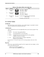
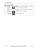
High and Low Limit Indication
When the high or low limit is exceeded, the lower display indicates the word “LIMIT”
(blinking). The PV is indicated in the upper display. This will continue until the Out-of-
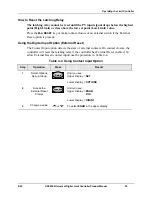
Limit condition exists and you reset the latching relay using the
M-A RESET
key or
through the Optional External Reset feature.
The Limit Relay
cannot
be reset while a Limit condition exists.
Summary of Contents for UDC2500 Limit
Page 2: ...ii UDC2500 Universal Digital Limit ControllerProduct Manual 8 05...
Page 10: ......
Page 76: ...Input Calibration 66 UDC2500 Universal Digital Limit ControllerProduct Manual 8 05...
Page 126: ......
Page 127: ......
Page 128: ......