


Configuration
8/05
UDC2500 Universal Digital Limit ControllerProduct
Manual
31
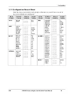
3.6 Input 1 Set Up Group
Introduction
This data deals with various parameters required to configure Input 1.
Function Prompts
Table 3-6
INPUT 1 Group Function Prompts
Function Prompt
Lower Display
Selection or Range of Setting
Upper Display
Parameter
Definition
IN1TYP
B
E H
E L
J H
J M
J L
K H
K M
K L
NNMH
NNML
NICH
NICL
R
S
T H
T L
W H
W L
100H
100L
200
500
RADH
RADI
0-20
4-20
10m
50m
100m
0-5
1-5
0-10
TDIF
INPUT 1 ACTUATION TYPE
– This
selection determines what actuation you are
going to use for Input 1.
B
—B Thermocouple
E H
—E Thermocouple High
E L
—E Thermocouple Low
J H
—J Thermocouple High
J M
—J Thermocouple Med
J L
—J Thermocouple Low
K H
—K Thermocouple High
K M
—K Thermocouple Med
K L
—K Thermocouple Low
NNMH
—Ni-Ni-Moly Thermocouple High
NNML
—Ni-Ni-Moly Thermocouple Low
NICH
—Nicrosil-Nisil Thermocouple High
NICL
—Nicrosil-Nisil Thermocouple Low
R
—R Thermocouple
S
—S Thermocouple
T H
—T Thermocouple High
T L
—T Thermocouple Low
W H
—W5W26 Thermocouple High
W L
—W5W26 Thermocouple Low
100H
—100 Ohm RTD High
100L
—100 Ohm RTD Low
200
—200 Ohm RTD
500
—500 Ohm RTD
RADH
—Radiamatic RH
RADI
—Radiamatic RI
0-20
—0 to 20 Milliamperes *
4-20
—4 to 20 Milliamperes *
10m
—0 to 10 Millivolts *
50m
—0 to 50 Millivolts *
100m
—0 to 100 Millivolts *
0-5
—0 to 5 Volts *
1-5
—1 to 5 Volts *
0-10
—0 to 10 Volts *
TDIF
—Thermocouple Differential *
* These input types are not available on
FM Models.
Summary of Contents for UDC2500 Limit
Page 2: ...ii UDC2500 Universal Digital Limit ControllerProduct Manual 8 05...
Page 10: ......
Page 76: ...Input Calibration 66 UDC2500 Universal Digital Limit ControllerProduct Manual 8 05...
Page 126: ......
Page 127: ......
Page 128: ......