


Installation
8/05
UDC2500 Universal Digital Limit ControllerProduct
Manual
25
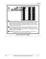
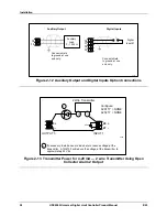
2 Wire Transmitter
_
+
INPUT 1
AUXILIARY OUTPUT
250
Ω
xxxx
26 +
27 -
12 +
13 -
Configure:
AUXOUT = OUT
Auxiliary Output Calibration
ZEROVAL = 4095
SPANVAL = 4095
If necessary, install a zener diode here to reduce voltage at the
transmitter. A 1N4733 will reduce the voltage at the transmitter to
approximately 25 Vdc.
1
1
Figure 2-14 Transmitter Power for 4-20 mA — 2 Wire Transmitter
Using Auxiliary Output
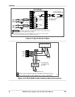
2.8 Limit Control Application Diagram
Limit Controller Wiring
Figure 2-15 shows the RIGHT and WRONG way to wire your Limit Controller.
PROCESS
CONTROLLER
LIMIT
CONTROLLER
PROCESS
CONTROLLER
LIMIT
CONTROLLER
CONTROL
RELAY/
SOLENOID
POWER
1
2
The Limit Controller
CANNOT
protect
against a failure of the Control relay
LOAD
POWER
1
2
CONTROL
RELAY/
SOLENOID
LOAD
POWER
POWER
The Limit Controller
CAN
protect
against a failure of the Control relay
WRONG
RIGHT
Figure 2-15 Limit Controller Application Diagram
Summary of Contents for UDC2500 Limit
Page 2: ...ii UDC2500 Universal Digital Limit ControllerProduct Manual 8 05...
Page 10: ......
Page 76: ...Input Calibration 66 UDC2500 Universal Digital Limit ControllerProduct Manual 8 05...
Page 126: ......
Page 127: ......
Page 128: ......