


Installation
24
UDC2500 Universal Digital Limit ControllerProduct Manual
8/05
12
13
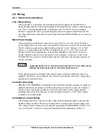
+
_
Auxiliary
Load
0 - 1000
Ω
Connect shield
to ground at one
end only.
Auxiliary Output
10
11
+
_
Digital
Input #1
Connect shield
to ground at one
end only.
Digital Inputs
12
13
xxxx
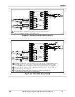
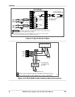
Figure 2-12 Auxiliary Output and Digital Inputs Option Connections
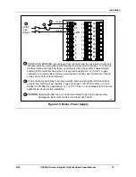
Configure:
A2S1TY = NONE
A2S2TY = NONE
2 Wire Transmitter
_
+
INPUT 1
OUTPUT 3
250
Ω
xxxx
26 +
27 -
5 +
6 -
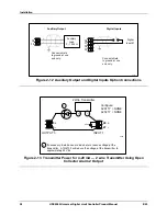
If necessary, install a zener diode here to reduce voltage at the
transmitter. A 1N4733 will reduce the voltage at the transmitter to
approximately 25 Vdc.
1
1
Figure 2-13 Transmitter Power for 4-20 mA — 2 wire Transmitter Using Open
Collector Alarm 2 Output
Summary of Contents for UDC2500 Limit
Page 2: ...ii UDC2500 Universal Digital Limit ControllerProduct Manual 8 05...
Page 10: ......
Page 76: ...Input Calibration 66 UDC2500 Universal Digital Limit ControllerProduct Manual 8 05...
Page 126: ......
Page 127: ......
Page 128: ......