


Introduction
8/05
UDC2500 Universal Digital Limit ControllerProduct Manual
1
1 Introduction
1.1 Overview
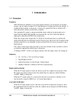
Function
UDC2500 Limit Controllers accept input signals from any of several types of external
sensors such as Thermocouples (T/Cs) and Resistance Temperature Detectors (RTDs). It
conditions these signals, as necessary, to derive the equivalent Process Variable (PV)
value that drives various circuits in the controller.
The equivalent PV signal is compared with the Limit control set point and any error
signal from the differential amplifier de-energizes the coil of an electromechanical,
single-pole, dual-throw (SPDT) limit output relay.
When de-energized, the output relay “Locks Out” and remains that way until the PV
input signal drops below the High Limit Set Point or goes above the Low Limit Set Point
and the controller is reset manually via the keyboard or from a remote location (Contact
Input Option).
The contact of the output relay terminates at the rear terminal of the controller to which
you make the appropriate field wiring connections.
A flashing “LIMIT” in the lower display indicates that the output relay is de-energized.
Features
•
90 – 264 Vac or 24 Vac/dc Power Supply
•
Input/Output Isolation
•
Isolated Auxiliary Current Output / Digital Inputs
•
Modbus
RS-485 or Ethernet TCP/IP Communications
High Limit Controller
When the PV input signal is below the limit set point, the output relay energizes. If the
PV signal exceeds the limit set point, the output relay de-energizes and the flashing
“LIMIT” display is turned on.
When the PV signal returns to a value below the limit set point, the controller can be
reset manually using the RESET key or Contact Input Option.
Low Limit Controller
When the PV input signal is above the limit set point, the output relay energizes. If the
PV signal falls below the limit set point, the output relay de-energizes and the flashing
“LIMIT” display is turned on.
Summary of Contents for UDC2500 Limit
Page 2: ...ii UDC2500 Universal Digital Limit ControllerProduct Manual 8 05...
Page 10: ......
Page 76: ...Input Calibration 66 UDC2500 Universal Digital Limit ControllerProduct Manual 8 05...
Page 126: ......
Page 127: ......
Page 128: ......