background image

Firmware V6.6.9

29.07.2020

146/147

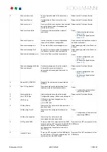
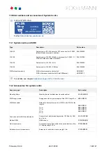
13 Order numbers and accessories of System Centre

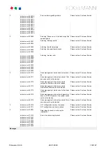
13.1  System centre and SIOX

Type

Description

Part number

CI 4000

System centre: S0 / M-bus meter, GLT, successor for CI 3000 
(without Modbus compact controller)

KGLCI4000E

CI 4100

System centre: CI 4000 + Modbus, successor for CI 3000 / CI 
3100 (with Modbus compact controller)

KGLCI4100E

CI 4400

System centre: CI 4100 + LAN

KGLCI4400E

CI 4500

System centre: CI 4400 + CAN bus

KGLCI4500E

SIOX extension module

SIOX without manual control switch 
SIOX with manual control switch (Auto/Off/Manual)

LISIOX0011
LISIOX0012

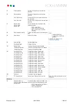
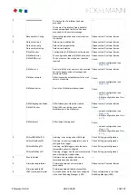
13.2  Accessories for system centre

Accessory part

Description

Part number

Mounting frame

Mounting frame for attachment in switch cabinet

KGLRAHMEN2

SIOX supply cable

Supply cable for the power supply of the SIOX, length 2 m

KABLIND006

SIOX data cable

Data cable from system centre or SIOX to the SIOX in the 
lengths:

0.4 m
0.7 m
2.0 m
5.0 m

KABLIND001
KABLIND002
KABLIND003
KABLIND007

Connector set for CAN bus terminatin

Connector set with terminating resistor 100 Ohm for CAN 
bus, 2 pcs.

KGLCANTERM

Modem GSM

GSM modem

PCZMODEM04

Null modem cable

For connecting the flash cable to the serial interface of the 

PC / laptop, length 3.0 m

PCZKABSER2

Extension for null modem cable

Extension for null modem cable, length 1.8 m

PCZKABSER3

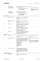
Visit our E*LDS shop:

Further 

https://ldsshop.eckelmann.de

For details, see chapter 

Expansion stages of the CI 4000 series

Summary of Contents for CI 4000 Series

Page 1: ...Firmware V6 6 9 29 07 2020 Docu 2 04 Operating instruction System Centre CI 4000 series The central of the E LDS system The series includes the following expansion stages CI 4000 CI 4100 CI 4400 CI 4500 ...

Page 2: ...ocumentation Platform at www eckelmann de elds You reach all relevant documents for this component directly using the QR code You reach all relevant documents for this component directly using the QR code https edp eckelmann de edp lds _a8DwY2ZwdN Information on safety and connection instructions are described in detail in chapter Industrial safety notes Copyright All rights to any use whatever ut...

Page 3: ...n 13 3 2 1 Communication interfaces 15 3 3 Version dependencies for other E LDS components 15 4 System centre functions 17 4 1 Tasks and functions 17 4 2 Expansion stages of the CI 4000 series 18 5 Function of System Centre 20 5 1 Starting Characteristics 20 5 1 1 First start Reset System 20 5 1 2 Restart Restart of the controller 20 5 2 Configuration of the E LDS system using the LDSWin PC softwa...
Page 4: ... 5 10 24h list 39 6 System Centre Installation and Start up 40 6 1 Installation System Centre 40 6 1 1 DIP Switches 41 6 2 DIN rail mounting SIOX Extension Module 42 6 2 1 SIOX connection to the system centre 42 6 2 2 SIOX configuration of the jumpers 43 6 2 3 SIOX connection of energy gas water and event meters 45 6 2 3 1 Calculation of consumption power from meter values 46 6 2 4 SIOX manual aut...

Page 5: ...l assignment of the 24 V AC DC 230 V AC digital inputs 67 7 2 2 SIOX Terminal assignment of the 230 V AC relay outputs 69 7 2 3 SIOX Terminal assignment of the interfaces 71 8 Operation and access to the system centre 73 9 Menus of the system centre 76 9 1 On site at the device 76 9 1 1 Layout of the touch screen 76 9 1 1 1 Status bar and quick info 77 9 1 1 2 Main menu and central controls 77 9 1...

Page 6: ...data 141 12 2 1 Dimensions 142 12 2 2 Control panel cut out 142 12 2 3 Mounting frame for control panel installation 144 12 2 4 SIOX extension module 145 12 3 Information on open source software 145 13 Order numbers and accessories of System Centre 146 13 1 System centre and SIOX 146 13 2 Accessories for system centre 146 ...

Page 7: ...on symbol can result in personal injury in extreme cases serious injuries or death and or material damage Voltage symbol warning of dangerous electrical voltage Warning of dangerous electrical voltage Danger of electric shock BEFORE connecting and disconnecting it must be checkedthat no voltage is present at the 230 V AC relay outputs Further information for the enclosure protection of the device ...

Page 8: ...lectrical voltage with possible consequences of serious injuries and death Failure to observe the voltagesymbol can result in personal injury in extreme cases serious injuries or death and or material damage If this symbol is seen the operating manual must be consulted to find out the type of the potential HAZARD and the required actions for the avoidance of the HAZARD 2 Symbol warning of electros...

Page 9: ...LDS system the accident prevention regulations and general safety regulations must be strictly complied with Important information safety instructions and hazard warnings are indicated by appropriate symbols see chapter Conventions Follow these instructions in order to prevent accidents and danger to life and limb as well as damage to the E LDS system Warning about dangerous electrical voltage Dan...

Page 10: ...cordance with the environmental conditions described in this operating manual Note the safety instructions and the instructions for installation and start up operation and maintenance Start the commissioning and or operation of the machine system AFTERWARDS The safety and the function of the machine system are only fulfilled with this intended use Never use the machine system its components assemb...

Page 11: ...ners and tabletops synthetic clothing footwear with plastic soles transparent covers polystyrene packaging monitors etc Wear work clothing made of cotton ESD footwear with electrically conductive soles or leather soles Use conductive floors ESD work places with the tools provided for them earthed soldering irons earthing wrist strap and similar conductive ESD bags conductive plastic containers IC ...

Page 12: ...llation and their retransmission by LAN modem or SMS can be realised The system centre is equipped with internal storage for data archiving of operating data and states alarms and messages energy data or for logging of temperature and EU archives HACCP Optionally up to maximum 4 extension modules SIOX Serial IO Extension can be connected so that an additional 48 digital inputs and 32 relay outputs...

Page 13: ... g an audible signalling unit The system centre can be expanded with up to max 4 SIOX extension modules For each SIOX 12 additional digital inputs for meters alarms etc and 8 additional relay outputs for week timers load shedding are available For details see chapter SIOX extension module for DIN rail mounting page 47 DIN rail mounting SIOX Extension Module The CI 4000 series does not have any dir...

Page 14: ...10 VS 300 pack controllers PC CAN bus adapter CI 4500 only Second CAN bus interface CAN2 for use as CAN bus repeater Interfaces left side Only CI 4100 or higher COM3 MODBUS RS485 interface on COMBICON terminal for direct connection of UA 30 Rx compact controllers LDS1 gateways Dixell so that the RS232 interface COM2 can be used for external controllers COM4 RS232 interface for Danfoss AHT Wurm AHT...

Page 15: ...tion to LDSWin X X X X USB Host USB 1 1 female connector A Firmware Update X X X X For details see chapter Terminal assignment of communication interfaces v6 0 3 3 Version dependencies for other E LDS components In order to guarantee faultless operation of the controller in the E LDS system the E LDS components must have the following software versions LDSWin Complete range of functions from Versi...

Page 16: ...7 UA 30 Rx series compact case controllers All control components are compatible all versions VS 301x series pack controllers All control components are compatible all versions WR 300 WR 400 receiver module All versions are compatible ...

Page 17: ...oller and of the E LDS system via two alarm contacts Prio 1 Prio 2 via audible internal signal generator buzzer Via optional configurable multifunction relay AUX parameter Horn and Alarm signalling by flashing the touchscreen when screensaver is activated Control of up to 8 relay outputs of a SIOX extension module using week timers Central time synchronisation time server The date and time can be ...

Page 18: ...mission of alarms via Pushover CI 4500 Functions Second CAN bus interface CAN2 for use as CAN bus repeater see chapter CAN bus Connection of E LDS Components 4 2 Expansion stages of the CI 4000 series On the hardware side the controller is always supplied in the complete design on the software side the individual expansion stages and the associated range of functions are enabled using a licence ke...
Page 19: ...ANT LAN Combi gateway must be removed from the E LDS system Details for the exchange repair and replacement of a CI 3x00 store computer can be found here X X Two CAN bus segments connection to terminals CAN1 and CAN2 with repeater function X Summary CI 4000 S0 M bus meter GLT successor for CI 3000 without Modbus compact controller CI 4100 CI 4000 Modbus successor for CI 3100 with Modbus compact co...

Page 20: ...omponent the configuration can be written back to the replacement device Further information for this can be found in the LDSWin operating instruction For local configuration the system centre is connected via null modem cable EAG No PCZKABSER2 to the PC laptop In addition for the purpose of remote adjustment and maintenance the system centre can also be operated using a PC via a modem and via a n...

Page 21: ...ntroller UA 30 RC UA 30 RS 1 50 50 Case controller via LDS1 gateway 1 48 Case controller Dixell 1 50 5 3 1 Integration of case controllers of the E LDS system Only CI 4100 or higher The following case controllers can be integrated and archived in the E LDS system via Modbus Connection to the system centre is made via the COM3 Modbus interface Compact case controllers Supported controllers UA 30 RC...

Page 22: ...he connection of the AHT cases to the system centre is made via the COM4 interface The system centre is used for showing the status and for the configuration of the integrated compact case controllers M1 M50 See Menu 2 2 for the status and display of the temperature of the individual refrigeration points See Menu 4 2 for configuration of name and position designation of the individual refrigeratio...

Page 23: ...put meter inputs Menu 4 1 1 Menu 4 1 6 see also chapter SIOX connection of energy gas water and event meters By using up to a maximum of 4 SIOX extension modules see chapter SIOX connection to the system centre the number of inputs can be increased by another 48 digital inputs 12 digital inputs for each SIOX module see Menu 4 1 1 Depending on the configuration and programming the number of digital...

Page 24: ...re use Menu 4 1 3 Detailed information about the configuration can be found in the chapter Alarm and message inputs The following special inputs are available Special input Function Shunt lock Detects whether the store is open or closed used for building control Emergency power supply Detects whether an emergency power generator has been activated and can be used to reduce the load The signal is c...

Page 25: ...C relay outputs In order to use these functions E LDS components must be used that also support these functions Details can be found in the operating manual of the respective E LDS component Alarm signalling failure In the event of the failure of a SIOX extension module with connected external alarms their monitoring also ceases The failure of a SIOX extension module signals an alarm But then no f...

Page 26: ...g after pressing the Horn button see chapter Menu 1 1 Alarms and messages no alarms with the corresponding priority are contained in the alarm list The alarm outputs are self holding with time delayed automatic alarm signalling in the event of power failure The current states of the outputs are maintained if the mains voltage of the controller is switched off for a short time If the controller rem...

Page 27: ... see Menu 4 1 1 Depending on the configuration and programming the number of relay outputs can be even further increased by using a GLT DDC controller Configuration Week timers with up to 7 control times see Menu 4 1 4 can be configured for each relay output The control times can be set accurate to the minute and on individual weekdays or weekday groups Control times authorised time period Weekday...

Page 28: ...edp eckelmann de edp lds _dGFHqz89xb 5 7 Alarms and messages The system centre is the collection point for alarms and messages of all E LDS components in the system The messages are listed in the alarm and message lists and can be called by the operator via Menu 1 The alarm list provides a quick overview of all currently pending alarms the message list shows the history of the faults that have occ...

Page 29: ... by tapping the Horn button in the main menu see chapter Menu 5 Horn 5 7 1 Explanation of terms for Alarms and Messages The following terms are used in connection with alarms and messages in this operating manual receive time stamp incoming date with time of the alarm message when this occurred arrived pending alarm message alarm message still present pending the cause defect error event has not y...

Page 30: ...vice can rectify on the next day 3 13 23 93 4 14 34 94 5 15 25 95 6 16 26 96 7 17 27 97 8 18 28 98 9 19 29 99 Low priority entry in alarm and message lists remote alarm is signalled local alarm is signalled horn triggering of the multi function relay AUX ONLY for one decade e g X3 This division into alarm groups decades facilitates maintenance group oriented alarm management For more information s...

Page 31: ...as compared with EASY alarm destinations The alarm destinations are freely configurable in LDSWin and can be assigned to any destinations Further information about the functions is contained in the chapter Priority concept The following settings are possible for these alarm destinations these are only displayed in the system centre Name of the alarm destination freely definable Destination type se...

Page 32: ...cation of alarm priorities X0 X9 in decades priority groups Refrigeration pack system X0 Heating X1 Air conditioning X2 X9 Horizontal Logical classification of alarms and messages for each alarm number The alarm priorities listed on the left are 0 10 20 90 interpreted as messages registered in the message list no alarm is signalled no signal tone is sounded buzzer 1 2 11 12 21 22 91 92 interpreted...

Page 33: ...alarms via modem The controller provides the possibility to automatically forward alarms and messages in plain text from the E LDS system via a modem to various destinations Menu 4 1 7 The following information is transmitted in the message Store name Message text Date and time of the receive or send time stamp Priority Telephone number of the store Position number CAN bus address and the name of ...

Page 34: ... fails this is detected by the station monitoring and the error message Computer failure xxx is generated Each new E LDS component connected to the CAN bus is detected automatically by the controller using plug and play and included in the station monitoring Menu 2 The following CAN bus nodes can be present in the E LDS system Risk of the failure of alarm messages via SMS and thus no alarm signall...

Page 35: ...led this is detected as failed by the station monitoring The following symbol is then shown in the status bar at the top right in the display of the system centre If the user taps on this symbol within 5 minutes see also chapter Status bar and quick info he has the possibility to declare the refrigeration point in the following screen as e g switched off If the confirmation is made in good time ye...

Page 36: ...uired It shows 20 load shedding stages that are prioritised in ascending order starting with stage 1 If load shedding is required Stage 1 is shed first If insufficient reaction is caused as a result of this the next Stage 2 20 is triggered This strategy is continued until either the power consumption falls into the neutral zone or the highest load shedding stage is reached escalation strategy Afte...

Page 37: ...m load shed time specifies the time that a stage must at least be shed for It may be loaded again afterwards If the time is parametrised to 0 it has no influence on the function of the LSM Maximum time load shed time A maximum load shed time can be configured using this parameter This time starts with the shedding of a stage If the configured maximum load shed time is reached the stage is loaded a...

Page 38: ...appropriate use of this input the load optimisation can be significantly improved as the LSM can determine an optimum load shedding strategy If this input is not configured for a stage power requirement of the consumer is always assumed The power demand input only has an effect on the loading of the respective stage The following diagram gives an overview of how the load management affects the var...

Page 39: ...ll temperature sensors without exception of the case controllers E LDS components and integrated external controllers located in the E LDS system are listed there together with their hourly temperature average value For further details see chapter Menü 3 24h Liste For temperature archives further in the past that should be shown the temperature archives must be called cyclically and saved on a PC ...

Page 40: ...is not intended as possible hazards from incorrect re assembly cannot be ruled out Opening the device is not authorised Furthermore it must be noted that the safety of the system or the installation in which the device is integrated is the responsibility of the creator of the system or installation If the device is used in any way not specified by Eckelmann AG the protection supported by the devic...

Page 41: ...asher nut 6 1 1 DIP Switches Default settings of the DIP switches The WDOG and BOOT DIP switches are located on the top side of the system centre housing and must be set as follows for normal operation The technical specifications for the dimensions for the mounting cut outs for the variants A and B are shown in detail in chapter Control panel cut out For details about the wiring see chapter Syste...

Page 42: ...IOX modules must be parameterised in menu 4 1 1 The SIOX modules are available in two versions without manual control switch with manual control switch to be able to switch the relay outputs manually see chapter SIOX manual automatic mode selection The modules are connected to the system centre via SIOX power supply cables and SIOX data cables see chapter SIOX connection to the system centre 6 2 1...

Page 43: ... ensure that the minimum bending radius is complied with and that the cables are not routed parallel to cables which have the potential to generate strong interference coupling Max permitted data cable length is 30 m CAT5 cables or better must always be used see chapter Accessories for system centre v6 0 ATTENTION DO NOT connect using the Ethernet network cable 6 2 2 SIOX configuration of the jump...

Page 44: ...f the jumpers must always be performed when no voltage is present and with the connectors at the inputs terminals A1 A2 L1 L2 detached as a voltage of 230 V AC can be present at these terminals under certain circumstances If 230 V AC is applied to an input that has been configured for 24 V AC this results in destruction of the extension module SIOX Wiring of the digital inputs 230 V AC The N condu...

Page 45: ...he power supply of the S0 interface Configuration of meter and transformer constant Menu 4 1 6 Meter constant pulses per kWh or m3 Transformer constant conversion ratio of current transformer Unit unit of measure kWh or m3 For further details see chapter Calculation of consumption power from meter values Connection and wiring examples for energy gas and water meters with a SIOX extension module Wa...

Page 46: ...y quantity consumption The number of pulses per kWh is determined The meter constant only needs to be set for pulse meters M bus meters do not have the meter constant Unit pulses kWh B Transformer constant Corresponds to the conversion ratio of the current transformer i e the relationship of the current through the consumer K L to the measuring current k l The setting of the transformer constant f...

Page 47: ...5 minutes power consumption of 48 kW has been determined An analogous calculation method is used for the consumption or flow rate of gas or water in this case in m3 or litres 6 2 4 SIOX manual automatic mode selection Depending on the design the SIOX extension modules have manual control switches so that the 8 relay outputs can be overridden manually The manual automatic mode selection is realised...

Page 48: ...usly I Manual ON If any switch is in the I position the controller registers the logical MANUAL OPERATION ON state The connected equipment is always controlled even if the software does not envisage this e g light remains on continuously 6 2 5 SIOX Status LEDs The I Manual OFF and I Manual ON positions override the state desired by the controller A message is generated if the Manual OFF and Manual...

Page 49: ...mmunication Check SIOX data cable if necessary OFF Error no communication Check SIOX data cable and SIOX power supply cables if necessary 6 3 CAN bus Connection of E LDS Components Depending on the expansion stage up to two CAN bus segments can be connected to the system centre CAN1 A First CAN bus segment Standard for up to 127 CAN bus nodes CAN2 B Second CAN bus segment Only CI 4500 System centr...

Page 50: ... it as quickly as possible Practical tip Until the system centre is reactivated again a CAN bus repeater can be used as a temporary solution to exchange information e g t0 suction pressure between the two CAN bus segments CAN1 and CAN2 The evaporator input sensor R5 x should also be connected in the t0 via CAN bus operating mode This results in improved emergency running characteristics in the eve...

Page 51: ... gateways with case controllers of the LDS1 system Dixell controllers for details see chapter Integration of external controllers For further details about pin assignments see chapter Terminal assignment of the COM3 Modbus terminals RS485 6 5 M bus Connection of gateways M bus meters such as energy gas heat or water meters can be connected to the system centre via the M bus gateway For this the M ...

Page 52: ...een supply voltage 11 28 V DC is applied Red overcurrent short circuit on the cable Yellow terminal device transmitting 6 6 Modem If a modem should be used for remote maintenance of the system centre and for the automatic transmission of alarms this must be connected to the COM1 port The 3 terminal pairs M M are used to distinguish between the M bus cables However the polarity for M bus installati...

Page 53: ...m power supply In order to do this the following settings must be configured in Menu 4 1 7 under Other Failure of transmission of alarms When using modems other than those obtained from Eckelmann AG trouble free operation of transmission of alarms and remote maintenance cannot be guaranteed After installation of the system centre and the modem as well as the configuration of the automatic transmis...

Page 54: ...Modem 6 6 3 FAX Transmission via ISDN Modem If the FAX transmission of alarms and messages is also needed as well as the alarm type on a PC with the LDSWIN PC software or the sending of SMS messages an analogue modem must be installed in the system 6 7 Switching on system centre The system centre is switched on by applying the mains voltage to the N L and PE terminals and to PE on the M4 screw For...

Page 55: ...1 5 As soon as the LDSWin PC software goes on line the system centre automatically switches from the mode m operating mode to the direct cable connection operating mode and the Direct cable connection message is registered in the alarm list Connection via CAN bus to PC adapter the CAN bus to PC adapter has been designed for use in the E LDS system It forms the interface between a service PC and th...

Page 56: ...ng VNC Virtual Network Computing 6 8 1 Status LEDs Ethernet Function Colour LED Description Ethernet green LED 1 ON Ethernet connection present Flashing data transfer yellow LED 2 ON 100 MBit s OFF 10 MBit s Information for the precise terminal assignment can be found in chapter System centre terminal diagram ...

Page 57: ...oltage message is displayed the controller must be sent to Eckelmann AG to guarantee correct replacement of the battery Opening the device is not authorised see chapter System Centre Installation and Start up 6 12 Firmware Update The system centre is supplied with the current firmware ready for operation Future software versions can be loaded into the system centre as required by means of a firmwa...

Page 58: ... For details see chapter Menu 4 1 9 Firmware Update Damage to the system and stock loss Before the firmware update the affected system component or the system must be brought into a safe state as the shutdown of the controller during the firmware update can have undesired effects on the system component and or the system Caution data loss The loading of software via firmware update must not be int...

Page 59: ... Terminal assignment of the 230 V AC power supply The connection is used for the power supply of the system centre and is located at the bottom on the device Warning about dangerous electrical voltage In order to guarantee reverse polarity protection only coded mating connectors may be used on the control component connections Warning about dangerous electrical voltage Danger of electric shock BEF...

Page 60: ...s disconnecting device for the device 7 1 2 Terminal assignment of the 230 V AC digital inputs The two digital inputs are designed for installation monitoring for special inputs and as measuring points meter inputs and are located at the bottom on the device Warning about dangerous electrical voltage Instruction for protective earthing The ground conductor must also be connected to the grounding s...

Page 61: ...anger of electric shock BEFORE connecting and disconnecting it must be checked that no voltage is present at the 230 V AC relay outputs Low voltage and safety extra low voltage must not be applied together at the relay outputs 15 16 18 25 26 28 and 35 36 38 If the alarm signalling is carried out using a telephone dialling device using the provided OFF delay alarm contacts PRIO1 PRIO2 these must be...

Page 62: ... to the first CAN bus segment CAN1 standard and second CAN bus segment CAN2 are located on the device at the bottom See chapter CAN bus Connection of E LDS Components for further details about the range of functions of the two interfaces DANGER Warning about dangerous electrical voltage If mains voltage is connected to the CAN bus terminals this will result in the destruction of all components con...

Page 63: ...rd CAN2 Second CAN bus segment Only CI 5500 Repeate function Terminal No Function Wire colour Terminal No Function Wire colour 1 2 3 4 SHLD Shield CAN GND CAN LOW CAN HIGH shield green brown white 21 22 23 24 SHLD Shield CAN GND CAN LOW CAN HIGH shield green brown white For details see chapter CAN bus Connection of E LDS Components and operating manual Basics and general safety and connection inst...

Page 64: ...dule Recommendation SIOX supply cables and SIOX data cables are available as accessories for the connection see chapter Accessories for system centre v6 0 7 1 6 Terminal assignment of the COM3 Modbus terminals RS485 Only CI 4100 or higher The connection is used for connecting UA 30 Dixell controllers and LDS1 gateways in the E LDS system and is located on the left side of the device The COM3 MODBU...

Page 65: ...s Modbus supply lines must be shielded cable type J Y ST Y 2x2x0 8 mm2 As a general rule care should be taken to ensure that signal cables and cables carrying mains voltage are routed in separate cable channels A terminating resistor of 100 ohms is already permanently installed integrated between terminals 33 and 34 in the system centre Thus any termination at these terminals must not be performed...

Page 66: ...Slave USB 2 0 female connector B For connection of a USB cable for the connection of the PC software LDSWin for details see Configuration of the E LDS system using Service PC locally E USB Host USB 1 1 female connector A For plugging in a USB stick for a firmware update for details see chapter Firmware Update F SIOX data cable RJ45 female connector Data cable for SIOX extension modules ATTENTION D...

Page 67: ...4 V DC AC 230 V AC available per SIOX extension module for system monitoring and or as measuring points meter inputs Warning about dangerous electrical voltage In order to guarantee reverse polarity protection only coded mating connectors may be used on the control component connections Warning about dangerous electrical voltage Danger of electric shock The configuration of the jumpers must always...

Page 68: ... J1 J2 is used as 24 V DC energy meter Note A power supply part number KGLNT23024 may be required for the supply of the meter Digital input Terminal No Function Without switch With switch 1 A1 A2 50 51 Alarm and message inputs e g for detection of external alarms Meter inputs for energy gas water and event Meter inputs for recording of the high and low tariff HT LT Synchronisation inputs for acqui...

Page 69: ...dule For example the outputs can be used as week timers e g for defrosting lighting car park lighting or for energy management e g load shedding or for enabling of consumers For extension modules with manual control switches see picture the outputs can be switched manually for details see chapter SIOX manual automatic mode selection The week timers are configured in Menu 4 1 4 Warning about danger...

Page 70: ...4 46 48 45 Normally open contacts Without switch With switch 5 53 54 13 14 6 63 64 23 24 7 73 74 33 34 8 83 84 43 44 COMBICON terminal blocks of the extension modules Without switch Changeover contacts 4 x 3 position COMBICON terminal blocks 4 x Normally open contacts 4 x 2 position COMBICON terminal blocks 4 x With switch Changeover contacts 1 x 12 position COMBICON terminal block 1 x Normally op...

Page 71: ... connection SIOX OUT Data port SIOX OUT RJ45 female connector Output of the SIOX data cable to the next SIOX connection SIOX IN Danger of destruction of components SIOX extension modules may only be connected to each other or the system centre when no voltage is present In the event of an Ethernet network cable with PoE Power over Ethernet being used instead of the SIOX data cable RJ45 damage can ...

Page 72: ... g energy meters Practical tip A separate power supply part number KGLNT23024 must be used for the supply of external consumers see chapter Accessories for system centre v6 0 93 94 Ground of 24 V DC 24 V DC Recommendation SIOX supply cables and SIOX data cables are available as accessories for the connection see chapter Accessories for system centre v6 0 ...

Page 73: ...erminal mode 2 LDSWin2 Serial connection via the USB Slave port type B A detailed description for PC direct connection via USB to the system centre can be found in E EDP 3 Serial connection via the COM1 interface1 4 Machine room and in the entire system Connection via CAN bus to PC adapter A detailed description can be found in E EDP 5 LAN connection A detailed description for PC direct connection...

Page 74: ...ase manufacturer Service store operator supply chains remote maintenance centres emergency services LDSWin2 Remote access via modem at the COM1 interface 8 Via Internet and LAN connection 9 VNC3 Via Internet and LAN connection using VNC see Remote operation of the system centre using VNC Virtual Network Computing ...

Page 75: ... should never be directly connected to the Internet 1 Not all possibilities for operation and access can be used simultaneously Further details for local operation can be found in chapter Configuration of the E LDS system using service PC locally page 44 Configuration of the E LDS system using Service PC locally 2 LDSWin Further details for local operation can be found in chapter Configuration of ...

Page 76: ...or display of all menus entry screens dialogue fields lists and diagrams Also the display of the on screen keyboard for input of parameters For details see chapter Main menu and central controls and On screen keyboards for input of parameters On screen keyboards for entry of parameters Navigation and other Depending on the respective menu or screen these areas are provided for navigation paging up...

Page 77: ...geration points have failed By tapping on the refrigeration points shown in the list they can be defined as unloaded refrigeration points that have either been switched off e g for cleaning and should be switched on again later or are defined as failed if the cause for why refrigeration points have failed is unknown e g when a fault is present For details see chapter Alarm suppression for manual s...

Page 78: ...rs 10 Field with status messages in the node list see Menu 2 2 or Button for tripping events e g for tripping a test alarm see chapter Menu 4 1 7 Alarm Signalling The Info field in the main menu contains the designation of the expansion stage of the system centre e g CI 4000 CI 4100 for details see chapter Expansion stages of the CI 4000 series The designation of the store e g Wiesbaden store is a...
Page 79: ...check left If the entry field has a red background right the input value is not plausible or not permitted and must be corrected Depending on the parameter characters are partially greyed out to prevent inadmissible input 3 Special keyboard for convenient input of time ranges e g for week timers ...

Page 80: ...owledgement of alarms only in the alarm list The display may have more icons than fit on the view and shows a list so that the views can be changed between by swiping right left and up down or by tapping buttons If necessary this is also indicated by arrow buttons for right left or up down Other elements Buttons to display other time periods in the 24h list for details see Menu 3 chapter Menu 3 24...

Page 81: ...g for restore of the factory settings User name Admin Password 0000 Equivalent in CI 3x00 not available See description After the login another symbol is shown automatically on the left next to the padlock this symbol is used in the service mode for suppression of the remote alarm signalling Symbol s Description The remote alarm signalling is active if the symbol is white If the symbol is yellow t...

Page 82: ...he following parameters Login Input Defaul t Delay min Input of the delay time for suppression of the remote alarm signalling The symbol is yellow if service mode has been activated Service mode is deactivated again by input of 0 minutes the symbol becomes white again and all alarms are then forwarded again immediately via modem network relays or horn 0 1 255 60 9 1 3 Remote control of E LDS compo...

Page 83: ...u contains a selection list with maximum ten menu items Other submenus or operating screens can be provided after the selection of a menu item Selection of the menu items Each line of this selection list in the display has a digit between 1 and 9 as well as 0 for menu item 10 with the associated name of the corresponding menu item The various menu items can be selected directly by tapping the nume...

Page 84: ...put of values and text Using the cursor buttons and the required line is selected that must then be confirmed using the ENTER button The cursor jumps to the input field Using the cursor buttons and or digit buttons values can now be entered and changed If the cursor buttons and are kept tapped the adjustment is made in high speed mode Text input For fields that enable input of texts the text input...

Page 85: ... has a title at the top left and is identified by prepended unique numbering Furthermore all buttons of the main menu and the submenus each have an individual number of 1 2 x at the bottom right to be able to reference the corresponding menus or entry screens in the operating manual Explanation of the numbering For example if the menu 4 1 5 Interface COM1 Modem is referenced in the operating manua...

Page 86: ...ew of other components Detailed information 2 5 6 EU archive Overview of EU archives Detailed information EU archive HACCP 2 6 7 Signal inputs Overview of signal inputs 2 7 8 Special inputs Overview of special inputs 2 8 9 General information 2 9 10 Log 2 10 3 24h list Overview of 24h list Temperature data of a refrigeration point 3 4 Configuration 4 Configuration System 4 Configuration Configurat...

Page 87: ...ate time 4 1 8 9 Firmware Update 4 1 9 10 System Information 4 1 10 11 System Reset 4 1 11 12 System Upgrade 4 1 12 2 Case controllers Configuration Case controllers Detailed information Remote control 4 2 3 Pack controllers Configuration Pack controllers Detailed information Remote control 4 3 4 Receiver module Wireless sensors Configuration Receiver module Wireless sensors Detailed information R...

Page 88: ...alarm list screen this does not show any entries then The Current Alarms view is displayed as default Use the left Message List tab button to change to the message list The message list contains all messages and current alarms with the priority 0 99 that have been listed by the system centre from connected E LDS components system wide and the activated external alarms signalled via the digital inp...

Page 89: ...urred receive time stamp Outgoing in the alarm list If any red alarm symbol can be seen in this column this means that alarms with the priority 1 9 are still pending the faults have not yet been rectified and these alarms cannot be acknowledged On the other hand if there is a date and time in this column the problems or causes of the alarm have been rectified and the alarm has gone and can be ackn...

Page 90: ...ssage Error number alarm or message text of the E LDS component Priority Message priority of the alarm 1 99 or message 0 10 20 90 2 Menu 2 Overview and monitoring of the system read only This button is used to call up the submenu for the system overview and the most important information name position address and the status In the submenu the most important status e g display of the current operat...

Page 91: ...al information Currently has no function 10 Log Log of the installation 1 Menu 2 1 Node Overview List of all available components in the E LDS system with node and position designations Also display of the assigned CAN bus address controller type firmware version and the priority The status is also visual 2 Menu 2 2 Case controllers List of all available case controllers in the E LDS system If a c...

Page 92: ...terminal mode screen In the terminal mode all parameters of the case controller can be viewed but not changed read only For more information see chapter Remote control of E LDS components terminal mode 3 Menu 2 3 Pack controllers List of all available pack controllers in the E LDS system If a pack controller is selected the following information can be retrieved via the corresponding screen node a...

Page 93: ...he pack controller can be viewed but not changed read only For more information see chapter Remote control of E LDS components terminal mode 4 Menu 2 4 Receiver Module Wireless Sensors List of all available receiver modules for wireless sensors in the E LDS system If a receiver module is selected the following information can be retrieved via the corresponding screen node and position designations...

Page 94: ...e information see chapter Remote control of E LDS components terminal mode 5 Menu 2 5 Other Components Overview List of all other E LDS components in the E LDS system If a component is selected the following information can be retrieved via the corresponding screen node and position designations message priority CAN bus address serial number firmware version Integrated via connected to CAN bus ter...

Page 95: ...mation see chapter Remote control of E LDS components terminal mode 6 Menu 2 6 EU Archive If the EU archiving has been configured for a coldroom controller and an assignment of the temperature sensors there to the sensors of a UA 300 L UA 410 L is made an EU archive is created for this sensor pair The available EU archives are displayed using this button A 24h list with temperatures in C in 15 min...

Page 96: ...s A1 A2 B1 B2 SIOX1 1st extension module inputs 1 12 SIOX2 2nd extension module inputs 1 12 SIOX3 3rd extension module inputs 1 12 SIOX4 4th extension module inputs 1 12 DDC1 1st GLT DDC module 1 DDC2 2nd GLT DDC module 2 DDC3 3rd GLT DDC module 3 DDC4 4th GLT DDC module 4 Note GLT Building Control System and DDC Digital Direct Control 8 Menu 2 8 Special Inputs The digital special inputs of the sy...

Page 97: ...odules inputs CI 4x00 system centre internal inputs IN1 IN2 terminals A1 A2 B1 B2 SIOX1 1 extension module inputs 1 12 SIOX2 2 extension module inputs 1 12 SIOX3 3 extension module inputs 1 12 SIOX4 4 extension module inputs 1 12 DDC1 1 GLT DDC module 1 DDC2 2 GLT DDC module 2 DDC3 3 GLT DDC module 3 DDC4 4 GLT DDC module 4 Note GLT building control and DDC Digital Direct Control 9 Menu 2 9 Genera...

Page 98: ...ure sensors without exception of the case controllers E LDS products and integrated external controllers located in the E LDS system are listed here together with their hourly temperature average value All case controllers can be considered within one day by tapping the up down buttons Tapping on a row shows a graphical display of the day Individual days can be changed between by tapping the left ...

Page 99: ...esponse is then only displayed if saving is not possible The submenu for configuration of the system is called using this button All E LDS components of the system can be configured in the submenus The submenu contains the following buttons here the buttons 1 8 in the first menu screen Button 9 in the second menu screen Brief description of the buttons 4 Configuration System 1 System centre Config...

Page 100: ...ntre The submenu for configuration of the system centre is called using this button The submenu contains the following buttons here the buttons 1 8 in the first menu screen Buttons 9 11 in the second menu screen Brief description of the buttons 4 Configuration System Centre 1 Expansion Configuration for expansion of the system centre 2 Signal inputs Configuration of the digital alarm and signal in...

Page 101: ...em X 1 4 read only Note Only visible if DDC modules are also connected 0 4 0 Operating mode for the 2nd CAN bus interface Setting of the operating mode for the 2nd CAN bus interface repeater Sync input Specification where the sync input for energy record is applied1 Sync input Module Module 1 to which the message alarm signal is applied SIOX1 SIOX4 Submodule XX Submodule 1 to which the message ala...

Page 102: ...oltage is present high active Y N Y Signal input Module Module 1 to which the message alarm signal is connected SIOX1 SIOX4 Submodule XX Submodule 1 to which the message alarm signal is applied this is ONLY visible if module DDC1 DDC4 has been selected 1 4 Input XX Input 1 to which the message alarm signal is applied 1 12 Status XX Current status of the input OK light grey no signalling Waiting ye...

Page 103: ...sec XX Delay time of the signal alarm in seconds 0 255 1 Quiescent current low active X Alarm is signalled if quiescent current Yes signal voltage not present low active quiescent current No signal voltage is present high active Y N N Signal input Module Module 1 to which the message alarm signal is connected SIOX1 SIOX4 Submodule XX Submodule 1 to which the message alarm signal is applied this is...

Page 104: ...put is then active if the current time is within any of the 7 configured control times The screen contains the following parameters Week timers Input Default Name Freely editable name designation of the week timer max 32 characters Control times Start Week timer start 00 00 23 59 08 00 End Week timer end 00 00 23 59 4 00 PM XXXXXXXXX Weekdays and groups of days Mon Fri Mon Sat Mon Sun Sat Sun Mon ...

Page 105: ...terfaces of the system centre is called using this button Configured values are displayed if available The list element is structured as follows CAN2 COM1 Modem COM2 COM3 Modbus COM4 Ethernet USB IP ports Interface CAN2 only CI 4500 The operating mode of the second CAN bus interface CAN2 is configured in this screen Only those SIOX modules and GLT PLC modules are provided for selection that have b...

Page 106: ... characters Dialling prefix Number for the outside line max 8 digits MSN 19 digit terminal device identification number for direct outside line this is the telephone number without the dialling prefix in the normal case i e for extensions this is the direct dial number max 19 characters 0 PIN PIN Alarm if modem not available Should an alarm be signalled if the modem is not detected If the check ma...

Page 107: ...configuration other parameters are shown for information Baud rate Baud rate 9600 Data bits Number of data bits 8 Parity Parity none Stop bits Number of stop bits 1 Handshake Handshake available none Interface Ethernet only CI 4400 or higher The Ethernet interface for the connection in a LAN is configured in this screen This interface is used for the data exchange and communication with LDSWin The...

Page 108: ...e Input Default LAN gateway Input of the TCP IP port for the LAN gateway Numbers 1 65535 5000 VNC server Input of the TCP IP port for the VNC server for details see chapter Remote control of the system centre via VNC Virtual Network Computing Numbers 1 65535 5900 Menu 4 1 6 Measuring points The submenu for configuration of the measuring points of the system centre is called using this button All i...

Page 109: ...ly for M bus meters If the Determine index automatically option is activated factory setting the meter value electricity kW water m etc to be archived is determined automatically If an alternative meter value should be archived the meter reading index must be configured for this The meter reading index can be determined using the Retrieve meter data button The meter indexes in the meter data can b...

Page 110: ...dule 1 to which the measuring point is connected this is ONLY visible if module DDC1 DDC4 has been selected 1 4 Input XX Input 1 to which the measuring point is connected 1 12 Status XX Current status of the measuring point Legend for the meter symbols used power water gas heating cooling oil and event 1 Designations of the supported modules inputs CI 4x00 system centre internal inputs IN1 IN2 ter...

Page 111: ...y For these alarm destinations the configured time ranges and special days are also displayed read only Time ranges of the system centre Specification of the special days Provider for SMS destinations Other definition of the mode of operation of the multi function relay AUX tripping a test alarm Extended alarm destinations 4 15 Pushover service Pushover service Input Default Application token Inpu...

Page 112: ...SMTP server max 40 characters Sender address Input of the E Mail address from which the error messages are sent max 40 characters Sender name Input of the sender name from which the error messages are sent max 40 characters Recipient address Input of the E Mail recipient address for the error message max 40 characters E Mail SMTP Alarms E Mail SMTP Alarms Input Default E Mail activated The check m...

Page 113: ...e range Messages are never within outside or always transmitted in the time range Never Within Outside Always Never LDSWin It is defined using this entry screen where the alarm is signalled in the event of a fault or which remote station with the LDSWin PC software is contacted ...

Page 114: ...essages with this priority will be transmitted None1 2 1 2 None Time range Messages are never within outside or always transmitted in the time range Never Within Outside Always Never Time ranges The time ranges duty hours at the Service Centre are defined using this entry screen New time ranges are defined using the New button a total of 3 time ranges can be entered For SMS Text Message Transmissi...

Page 115: ...he screen contains the following parameters Alarm signalling provider 1 2 Entry Default Description Description of the provider 1 2 e g D2 Max 19 characters Telephone number Telephone number of the provider 1 2 Protocol SMS protocol of the provider 1 2 NOTE This must be requested from the provider TAP UCP TAP Other The mode of operation of the multi function relay AUX is configured using this entr...

Page 116: ...parameters Alarm destination 4 15 Entry Default Description Description of the alarm destination e g Service 2 Telephone number Telephone number of the alarm destination Priority A Priority A Priority B Priority B Time range Messages are never within outside or always transmitted in the time range Possible values are Never Within Outside Always Never Menu 4 1 8 Date Time The entry screen for confi...

Page 117: ... Can the USB stick be read Are the required files for the boot loader firmware update on the USB stick in the correct directory 2 Update of the firmware The Update of the firmware check box is enabled for the update after the tests mentioned above have been successfully passed Y N N Any change of the time zone or the date results in inconsistencies in the data archiving as the assignment of the re...

Page 118: ...rchived operating data of the following node groups Case controllers on the CAN bus Case controllers on the Modbus Pack controllers BCT building control technology Y N Master Deletion of the energy archives Deletion of all archived energy data of the following node groups SO meters M bus meters Y N Deletion of the alarm and message lists Deletion of all entries in the alarm and message lists Y N D...

Page 119: ...rs System Upgrade Input Login required as Master MAC address Display of the MAC address Device dependent Licence key Input of the licence key Numbers and hyphen Example 1234 1234 1234 1234 2 Menu 4 2 Case controllers The submenu for configuration of the case controllers is called using this button All important parameters and the status of the case controllers are displayed there Case controllers ...

Page 120: ...are version of the controller Integrated using The controller is connected to the system centre via this interface Pack number Pack membership for the pack Remote control using terminal mode The terminal mode screen is opened using the Remote Control button All parameters of the case controller can be configured in the terminal mode For more information see chapter Remote control of E LDS componen...

Page 121: ... has been unloaded The status of the node is OK The node has alarm status The screen contains the following parameters Configuration Pack Controller Entry Default Name Name of the node e g Deep freeze pack max 19 characters Position Position designation of the node e g VSTK_01 5 characters Priority Alarm and message priority 0 99 0 99 Address CAN bus address 101 109 These fields cannot be edited S...

Page 122: ...eaning The status of the connection communication with the node is OK The status of the connection communication with the node is unknown The node has failed The node has been unloaded The status of the node is OK The node has alarm status The screen contains the following parameters Configuration Pack Controller Entry Default Name Name of the node e g Receiver_module_01 max 19 characters Position...

Page 123: ...h specification of the hyperlink where further information about the use of Open Source software components Licence Reports is described in detail for the present product Link to E EDP of Eckelmann AG https edp eckelmann de edp lds _V0brLLadsi 6 Menu 4 6 Users The screen for user management of the system centre is called up using this button All users created in the system are displayed there The ...

Page 124: ...at any time during running operation Each language in the selection list is displayed in its own language as well as in English The following languages can be selected German English French Italian Czech 9 Menu 4 9 Other Components The submenu for configuration of other E LDS components is called using this button If a component has been selected its Name parameter can be changed system wide using...

Page 125: ...edited Serial number Serial number of the controller Firmware version Firmware version of the controller Integrated using The controller is connected to the system centre via this interface Pack number Pack membership for the pack The following components are displayed CI 4000 Operator terminals e g AL 300 CI 400 LAN gateway software module Remote control using terminal mode The terminal mode scre...

Page 126: ...graphically Legend of the meter symbols Energy water gas heat oil and event Every line entry in the screen contains the following parameters Type and name of the meter its position designation the meter and transformer constants and the unit of measure Note Meters must be created and configured in Menu 4 1 6 otherwise they are not displayed in this screen Select a meter in the list to display the ...

Page 127: ...signation the meter and transformer constants and the unit of measure Note Meters must be created and configured in Menu 4 1 6 otherwise they are not displayed in this screen The required meter in the list must be selected to display the load profile of a meter The load profile of the current day is shown initially Individual time periods can be changed between by pressing the left right buttons 7...

Page 128: ...m After starting the VNC viewer the IP address of the system centre must be entered in the VNC Server configuration field The connection is then established by clicking with the mouse on the Connect button Example 1 Establishment of a VNC connection to the system centre with the IP address 10 0 28 27 If the VNC port has been changed see Menu 4 1 5 page 105 the new port must be explicitly appended ...

Page 129: ...Firmware V6 6 9 29 07 2020 129 147 After establishment of the VNC connection it is possible to operate the system centre using the PC keyboard and mouse ...

Page 130: ...9 07 2020 130 147 If the system centre is not operated for a longer time the screen saver for protection of the display is activated If a VNC connection exists the screen saver is deactivated with the first mouse click ...

Page 131: ...statutory regulations based on the Directive 2012 19 EU WEEE2 on waste electrical and electronic equipment Ensure the environmentally friendly disposal of the packaging the product and its components at the end of their service life Observe the applicable national regulations and laws DANGER Warning of dangerous electrical voltage Danger of electric shock During dismantling the same safety instruc...

Page 132: ...mer Service 46 Time difference The stored time in the real time clock is lost during system start CAN bus fault 41 CAN bus overflow Communication fault on the CAN bus or short circuit between CAN H and CAN L Check Wiring of the CAN bus CAN bus length max 500 m No branch lines CAN GND must be available everywhere CAN bus termination 100 ohms Colour scheme complied with Correct cable type LiYCY 2 x ...

Page 133: ...ustomer Service internal error 44 2711 Node management at least one stored CAN bus node could not be loaded Please contact Customer Service internal error 44 2712 Node management at least one stored compact controller could not be loaded Please contact Customer Service internal error 44 2713 Node management at least one stored Danfoss controller could not be loaded Please contact Customer Service ...

Page 134: ...il send error Error in the E Mail alarm transmission Check network configuration see Menu 4 1 5 E Mail configuration see Menu 4 1 7 E Mail language definition E Mail message could not be created Please contact Customer Service E Mail SSL error E Mail SSL error during connection establishment to the mail server Check network configuration see Menu 4 1 5 E Mail configuration see Menu 4 1 7 E Mail ti...

Page 135: ...ntact Customer Service Pushover timeout A timeout has occurred during the transmission of messages and alarms via Pushover Check network configuration see Menu 4 1 5 Pushover configuration see Menu 4 1 7 0 Reboot ANF_SERVICE Reboot of the system centre requested via LDSWin 0 Sum Z Ung Zaehler No power data could be determined for at least one meter in the totaliser module Check Configuration of th...

Page 136: ...e energy data Archiving Energy data deleted 241 VerstKonfig Al Ein Configuration change Signal inputs VerstKonfig Alm Cfg Configuration change Alarm settings VerstKonfig Lastab Configuration change Load shedding VerstKonfig M Zlr Configuration change M bus meter VerstKonfig Modem Configuration change Modem settings VerstKonfig MrCfg Configuration change System centre VerstKonfig Netzw Configuratio...

Page 137: ...tablished to the system centre The number of the LDSWin dongle is displayed as message text Dial in LAN A connection to LDSWin has been established using the network LAN to the system centre The number of the LDSWin dongle is displayed as message text Modem error 85 Modem fault The modem is not detected not switched on or not connected Modem and check connection to the system centre 86 Error alarm...

Page 138: ...f component Mxx defective Check component Mxx 10 Batteriefehler Mxx Battery fault on component Mxx Check component Mxx 124 Coldroom door Mxx Coldroom door of component Mxx open Close coldroom door check door contact and cable connections 126 Defrost thermostat Mxx or temporal defrost Mxx Defrost thermostat fault at component Mxx or Defrost end time at component Mxx Check component Mxx 128 Sensor f...

Page 139: ...ical interference has occurred Check connection cable Check shield Replace affected sensor 132 High temp Wxx High low temperature at component Wxx Parametrisation Temperature sensor Check system Other 180 Service Mode The automatic transmission of alarms has been deactivated temporarily for maintenance purposes Reset Service Mode see chapter Servic e Mode Suppression of remote alarm signalling xxx...

Page 140: ... 6 A inductive max 3 A cos phi 0 4 Manual control switch The SIOX extension modules have manual control switches so that the regulation can be overridden in emergency operation see chapter S IOX manual automatic mode selection Field bus interface CAN bus floating output Data ports 1x data port for SIOX Internal interface for the system centre 3 x seriell RS232 1x seriell RS485 Archive memory Compr...

Page 141: ...068 2 6 Transport and operation 2 g Atmospheric pressure Transport 660 hPa 1060 hPa Operation 860 hPa 1060 hPa Standards and Directives Protection rating IP20 EN 60529 CE conformity according to see https edp eckelmann de edp lds _aftpgg7so5 Low Voltage Directive 2014 35 EU Official Journal of the EU L96 29 03 2014 pages 357 374 EMC Directive 2014 30 EU Official Journal of the EU L96 29 03 2014 pa...

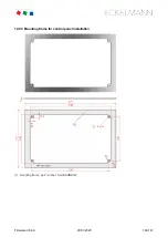
Page 142: ... attractive solution with somewhat complex manufacture of the panel cut out and the 4 x 4 mm holes Variant B The rectangular panel cut out can be realised quickly with a jigsaw e g during commissioning service however a mounting frame is needed for installation see chapter Einbaurahmen zur Schalttafelmontage ...

Page 143: ...Firmware V6 6 9 29 07 2020 143 147 ...

Page 144: ...Firmware V6 6 9 29 07 2020 144 147 12 2 3 Mounting frame for control panel installation 1 mounting frame part number KGLRAHMEN2 ...

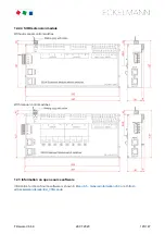
Page 145: ...xtension module Without manual control switches With manual control switches 12 3 Information on open source software Information for Open Source software is shown in Menu 4 5 General Information v6 0 or at https edp eckelmann de edp lds _V0brLLadsi ...

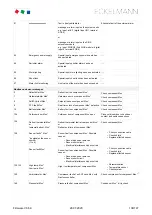
Page 146: ...re Accessory part Description Part number Mounting frame Mounting frame for attachment in switch cabinet KGLRAHMEN2 SIOX supply cable Supply cable for the power supply of the SIOX length 2 m KABLIND006 SIOX data cable Data cable from system centre or SIOX to the SIOX in the lengths 0 4 m 0 7 m 2 0 m 5 0 m KABLIND001 KABLIND002 KABLIND003 KABLIND007 Connector set for CAN bus terminatin Connector se...

Page 147: ...ith Danfoss SLV controllers For AHT chest freezers with Wurm controllers For AHT chest freezers with Danfoss SLV and Wurm controllers KGLAHTAD01 KGLAHTAD02 KGLAHTAD03 M bus gateway For consumption data capture including serial interface cable an external power supply KGLNT23024 is required M bus Gateway 20 max 20 M bus meters M bus Gateway 60 max 60 M bus meters KGLZMBUS01 KGLZMBUS02 Power supply ...

Reviews: