background image

Echoflex Installation Guide

Elaho Preset Station

Preset Stations connect to the EchoConnect communication bus.
EchoConnect is a bi-directional protocol that uses one pair of wires
(data+ and data–) for both data and power. Echoflex recommends using
Belden 8471 Class 2 wire (or approved equal – see the Echoflex cable
cross database

echoflexsolutions.com/files/Elaho_Data_Cable_Wire_

Specs

for equal alternatives). The total combined length of an

EchoConnect wire run using Belden 8471 may not exceed 500 m
(1,640 ft), with a maximum distance of 400 m (1,312 ft) between any two
devices.

Note:

All control wiring should be installed and terminated by a

qualified installer and should follow standard wiring installation
practices. Leave approximately 25.4 cm (10 in) of wiring in the
back box for connection and to allow slack for future service
needs.

Note:

Echoflex requires that all stations and devices be grounded

for ESD protection. Pull an additional 2.5 mm

2

(14 AWG) wire for

grounding when control wires are not installed in grounded metal
conduit.

Environmental

For indoor installation only; 0°C–50°C (32°F–122°F), 5%-95% non-
condensing humidity.

Address &
Space

DIP
switches

Rotary and DIP Switches

Rotary and DIP switch settings are accessible on the
back side of the station.

Set Space and Address

The Preset Station participates in an Elaho system using
the configured Space and Address, which are selectable
using the two rotary switches on the back of the
station. Each station must be set to a unique station
address for the assigned space.

Elaho Preset Station

Page 2 of 8

Echoflex

Summary of Contents for Elaho Preset Station

Page 1: ...des you through the installation and local configuration of the Preset Station Advanced custom functionality is available using ElahoAccess Custom Configuration For information about the custom config...

Page 2: ...d wiring installation practices Leave approximately 25 4 cm 10 in of wiring in the back box for connection and to allow slack for future service needs Note Echoflex requires that all stations and devi...

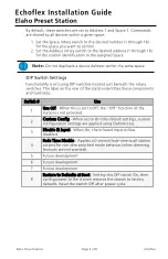
Page 3: ...on the rear of the station identifies these components and functions Switch Use 1 Use Off When this is set to Off the Off function of the station is not provided 2 Custom Config When set to On the def...

Page 4: ...g Cat5 careful planning is required to ensure the proper termination kits are available and the wire is pulled appropriately Connect Wiring 1 Pull all required wiring data data and an additional 2 5 m...

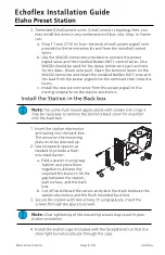
Page 5: ...nstall the Station in the Back box Note For some flush mount applications with certain trim rings it may be necessary to remove the station s back cover for insertion into the back box 1 3 2 4 1 Inser...

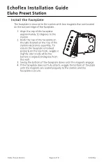
Page 6: ...ceplate on the tabs located on the top of the station electronics assembly To ensure the faceplate is hooked properly on the top hook wiggle it slightly side to side while the bottom is angled 20 degr...

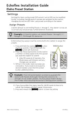
Page 7: ...s The LED beneath the MODE button will illuminate 2 Press the first preset button on the station a number of times equal to the first preset you want the station to control After 90 seconds of inactiv...

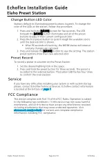
Page 8: ...ord To record a preset to a button on the Preset Station 1 Set the desired lighting look in the space 2 Press and hold the preset button for three seconds The preset is recorded to the selected button...

Reviews: