background image

Chengdu Ebyte Electronic Technology Co., Ltd.

E73-2G4M08S1C User Manual

Copyright ©2012–2018

Chengdu Ebyte Electronic Technology Co., Ltd

8

5 Basic operation

5.1 Hardware design

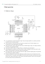
It is recommended to use a DC stabilized power supply. The power supply ripple factor is as small as possible and
the module needs to be reliably grounded.

Please pay attention to the correct connection of the positive and negative poles of the power supply, reverse
connection may cause permanent damage to the module.

Please check the power supply to ensure that between the recommended supply voltage, if exceeding the maximum,
the module will be permanently damaged;

Please check the stability of the power supply. Voltage can not fluctuate greatly and frequently;

When designing the power supply circuit for the module, it is often recommended to reserve more than 30% of the
margin, so the whole machine is beneficial for long-term stable operation;

The module should be as far away as possible from the power supply, transformers, high-frequency wiring and other
parts with large electromagnetic interference;

Bottom Layer High-frequency digital routing, high-frequency analog routing, and power routing must be avoided
under the module. If it is necessary to pass through the module, assume that the module is soldered to the Top Layer,
and the copper is spread on the Top Layer of the module contact part(well grounded), it must be close to the digital
part of the module and routed in the Bottom Layer;

Summary of Contents for E73-2GM08S1C

Page 1: ...E73 2G4M08S1C User Manual nRF52840 2 4GHz SMD Wireless Module ...

Page 2: ... 3 2 1 Limit parameter 3 2 2 Operating parameter 3 3 Size and pin definition 5 4 Development and Application 7 5 Basic operation 8 5 1 Hardware design 8 6 FAQ 9 6 1 Communication range is too short 9 6 2Module is easy to damage 9 6 3 BER Bit Error Rate is high 10 7 Production guidance 10 7 1 Reflow soldering temperature 10 7 2 Reflow soldering curve 11 8 E73 series 11 9 Antenna recommendation 12 9...

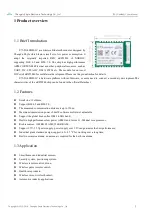
Page 3: ...ndary development The characteristics of the nRF52840 chip can be found in the official Datasheet 1 2 Features Small size 13x18mm Support BLE4 2 and BLE 5 0 The measured communication distance is up to 120m Maximum transmission power of 6mW software multi level adjustable Support the global license free ISM 2 4GHz band Built in high performance low power ARM and Cortex M4 dual core processor Rich ...

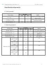
Page 4: ...in short distance Operating temperature 40 85 2 2 Operating parameter Main parameter Performance Remark Min Type Max Operating voltage V 1 7 3 3 5 5 3 3 V ensures output power Communication level V 3 3 For 5V TTL it may be at risk of burning down Operating temperature 40 85 Industrial grade Operating frequency GHz 2360 2500 Support ISM band Transmitting current TX only run current DC DC 3 V PRF 8 ...

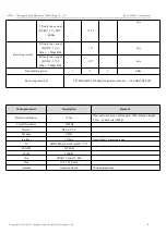
Page 5: ...bps 2 Mbps BLE 8 27 mA Transmitting power 7 8 9 dBm Receiving sensitivity 103 dBm BLE 125kbps long distance mode 95 dBm BLE 1M Main parameter Description Remark Reference distance 120m Clear and open area antenna gain 5dBi antenna height 2 5m air data rate 1Mbps Crystal Oscillator 32MHz Protocol BLE 4 2 5 0 Package SMD Interface 1 27mm Stamp hole Ceramic antenna IC nRF52840 QIAAC0 aQFN 73 FLASH 10...

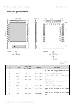
Page 6: ...datasheet on Nordic website 2 P1 10 P1 10 Common I O Low frequency I O standard drive 3 P0 03 P0 03 AIN1 Common I O Analog input 1 low frequency I O standard drive 4 AI4 P0 28 AIN4 Common I O Analog input 4 5 GND Single ground line connect to the power reference ground 6 P1 13 P1 13 Common I O Low frequency I O standard drive 7 AI0 P0 02 AIN0 Common I O Analog input 0 low frequency I O standard dr...

Page 7: ...mmon I O Analog input 2 19 VDD Power supply 20 P12 P0 12 Common I O See details about nrf52840 datasheet on Nordic website 21 GND ground line connect to the power reference ground 22 P0 07 P0 07 Common I O See details about nrf52840 datasheet on Nordic website 23 VDH VDDH High voltage power supply 24 GND ground line connect to the power reference ground 25 DCH DCCH DC DC Converter output 26 RST P0...

Page 8: ...tes 1 Burn Firmware 1 The module is embedded with ARM MCU For program downloading please use the J LINK downloader Any other serial port or JTAG ISP ICP are unavailable to download 1 The burn firmware needs to be completed in two parts Since the protocol stack provided by NORDIC is not loaded in the program in the second development you need to use the official burning tool nRFgo studio to burn th...

Page 9: ...amaged Please check the stability of the power supply Voltage can not fluctuate greatly and frequently When designing the power supply circuit for the module it is often recommended to reserve more than 30 of the margin so the whole machine is beneficial for long term stable operation The module should be as far away as possible from the power supply transformers high frequency wiring and other pa...

Page 10: ...s mounted inside the case use a good antenna extension cable to extend the antenna to the outside The antenna must not be installed inside the metal case which will cause the transmission distance to be greatly weakened 6 FAQ 6 1 Communication range is too short The communication distance will be affected when obstacle exists Data lose rate will be affected by temperature humidity and co channel i...

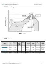
Page 11: ...emperature Profile Feature 曲线特征 Sn Pb Assembly Pb Free Assembly Solder Paste Solder paste Sn63 Pb37 Sn96 5 Ag3 Cu0 5 Preheat Temperature min Tsmin Min preheating temp 100 150 Preheat temperature max Tsmax Max preheating temp 150 200 Preheat Time Tsmin to Tsmax ts Preheating time 60 120 sec 60 120 sec Average ramp up rate Tsmax to Tp Average ramp up rate 3 second max 3 second max Liquidous Temperat...

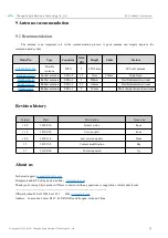
Page 12: ...ries Model IC Frequency Hz Tx power dBm Distance km Protocol Package Size mm Antenna E73 2G4M08S1C nRF52840 2 4G 8 0 1 BLE 4 2 5 0 SMD 13 0 18 0 Ceramic antenna Sta mp hole E73 2G4M04S1A nRF52810 2 4G 4 0 1 BLE 4 2 5 0 SMD 17 5 28 7 PCB IPX E73 2G4M04S1D nRF51822 2 4G 4 0 1 BLE 4 2 SMD 17 5 28 7 PCB IPX E73 2G4M04S1B nRF52832 2 4G 4 0 1 BLE 4 2 5 0 SMD 17 5 28 7 PCB IPX ...

Page 13: ...lexible omnidirectional TX2400 JK 11 Rubber antenna SMA J 2 5 110mm Flexible omnidirectional TX2400 JZ 3 Rubber antenna SMA J 2 30mm Short straight omnidirectional Revision history Version Date Description Issued by 1 00 2018 8 30 Initial version huaa 1 10 2018 9 28 Version split huaa 1 40 2018 11 6 new version update Huaa 1 5 2019 2 19 Content modification Ray 1 7 2019 8 20 Contect updated lyl Ab...

Page 14: ...Chengdu Ebyte Electronic Technology Co Ltd E73 2G4M08S1C User Manual Copyright 2012 2018 Chengdu Ebyte Electronic Technology Co Ltd 13 ...

Reviews: