Chengdu Ebyte Electronic Technology Co.,Ltd.
E70-433T
series User Manual
Copyright ©2012–2020
39
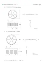
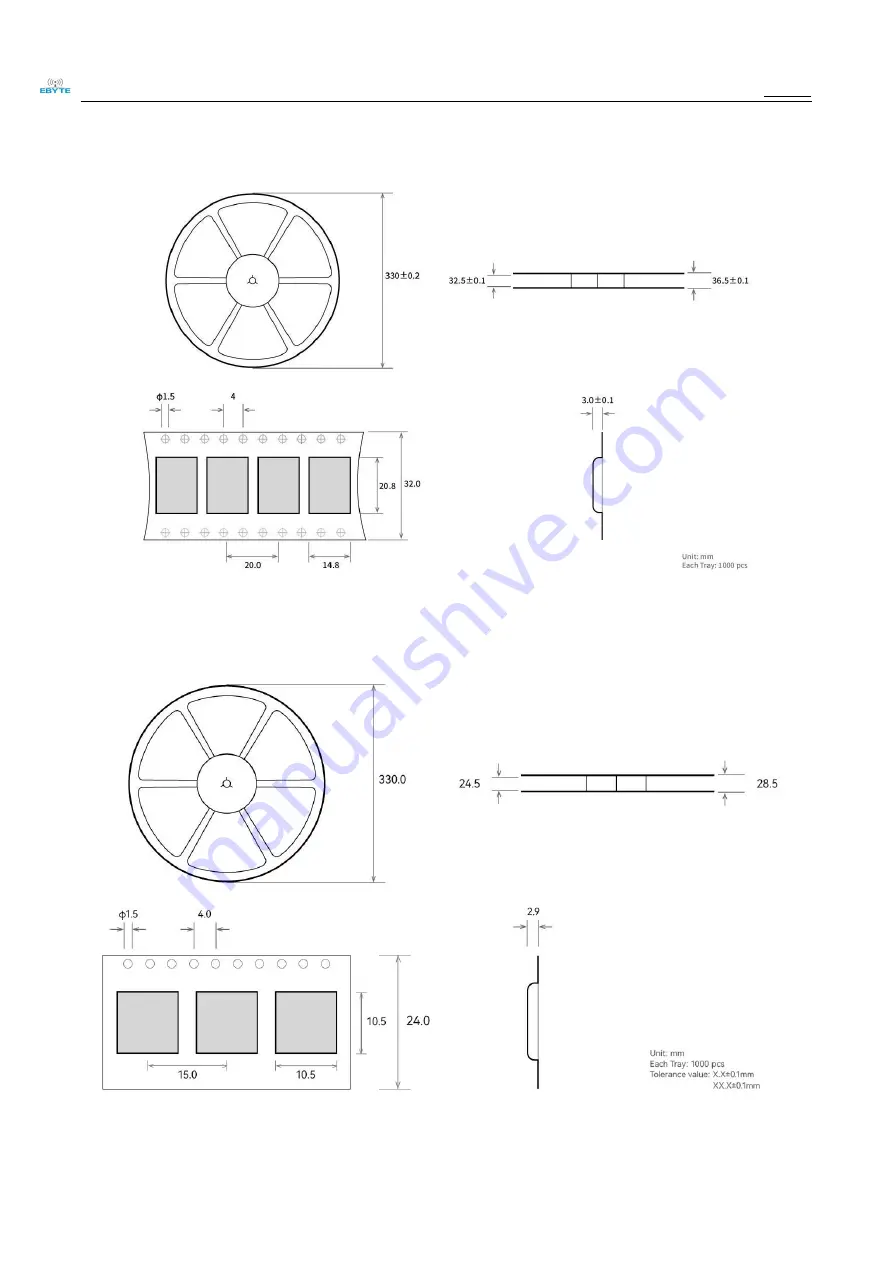
15. 3 E70-433T14S2 bulk packaging
15. 4 E70-433MT14S bulk packing
Page 1: ...E70 433T seriesUser Manual CC1310 433MHz TTL high speed continuous transmission wireless module...
Page 2: ...NS 18 CHAPTER 4 RECOMMENDED WIRING DIAGRAMS 19 CHAPTER 5 DETAILED EXPLANATION OF FUNCTIONS 20 5 1 FIXED POINT LAUNCH 1IN BASE 6 20 5 2 BROADCAST TRANSMISSION 16 BASE 21 5 3 BROADCAST ADDRESS 21 5 4 LI...
Page 3: ...E IS NOT IDEAL 33 11 2 MODULES ARE PRONE TO BREAKAGE 34 11 3 THE BIT ERROR RATE IS TOO HIGH 34 CHAPTER 12 WELDING OPERATION INSTRUCTIONS 34 12 1 REFLOW SOLDERING TEMPERATURE 34 12 2 REFLOW SOLDERING C...
Page 4: ...oduction use modification or disclosure to third parties of this document or any part thereof without the express permission of EBYTE is strictly prohibited The information contained herein is provide...
Page 5: ...sion functions and the data transmitted by the module in the air is random and the data interception is meaningless through strict encryption and decryption algorithms The data compression function ha...
Page 6: ...E70 433T30S built in PA LNA transmission power 1W communication distance up to 6km Supports the global license free ISM 433MHz band Support 2 5K 168kbps air transmission rate Support 2 2 3 8V power su...
Page 7: ...ansfer Modes for details 2 2 Electrical parameters Electrical parameters unit Model remark E70 433T30S E70 433T14S E70 433T14S 2 E70 433MT1 4S Operating voltage V 2 6 5 5 2 2 3 8 2 2 3 8 2 2 3 8 The E...
Page 8: ...defined FLASH 128 KB RAM 8 KB kernel Cortex M3 MCU Cortex M0 RF Communication interface UART serial port TTL level Modulation method GFSK Encapsulation method SMD Antenna interface IPEX stamp hole IPE...
Page 9: ...S dimensional drawing and pin definition Pin serial number Pin name Pin orientation Pin usage 1 GND Referential Module ground 2 GND Referential Module ground 3 GND Referential Module ground 4 NC Reser...
Page 10: ...M0 determines the module s 8 operating modes which require a 1K protection resistor in series 17 GND Referential Module ground 18 M0 input The combination of M2M1M0 determines the module s 8 operating...
Page 11: ...reservation is unused and needs to be left empty 33 NC Reserved feet The reservation is unused and needs to be left empty 34 NC Reserved feet The reservation is unused and needs to be left empty 35 NC...
Page 12: ...echnology Co Ltd 11 3 2 E70 433T14S dimensional drawing and pin definition 46 GND Referential Module ground 47 GND Referential Module ground 48 ANT Antenna 50 ohm characteristic impedance Pin serial n...
Page 13: ...e unused need to dangling 11 NC Keep your feet Leave unused need to dangling 12 NC Keep your feet Leave unused need to dangling 13 NC Keep your feet Leave unused need to dangling 14 NC Keep your feet...
Page 14: ...feet Leave unused need to dangling 25 AUX output Indicates the working status of the module the user wakes up the external MCU the output is low during power on self test initialization and can be con...
Page 15: ...r feet Leave unused need to dangling 36 NC Keep your feet Leave unused need to dangling 37 NC Keep your feet Leave unused need to dangling 38 NC Keep your feet Leave unused need to dangling 39 NC Keep...
Page 16: ...33T14S2 dimensional drawing and pin definition Pin serial number Pin name Pin orientat ion Pin usage 1 GND Referent ial Module ground 2 GND Referent ial Module ground 3 GND Referent ial Module ground...
Page 17: ...e the working status of the module the user wakes up the external MCU and the output is low during power on self test initialization which can be configured Set as an open drain output or push pull ou...
Page 18: ...nput output Antenna interface stamp hole 50 characteristic impedance 7 GND Referential Ground connected to the power supply reference ground 8 NC Keep your feet Leave unused need to dangling 9 NC Keep...
Page 19: ...nation of M2M1M0 determines the 8 operating modes of the module and an external 1K protection resistor is required in series when used 19 M1 input The combination of M2M1M0 determines the 8 operating...
Page 20: ...Chengdu Ebaite Electronic Technology Co Ltd E70 433TseriesProduct specifications Copyright 2012 2020 Chengdu Ebyte Electronic Technology Co Ltd 19 Chapter 4 Recommended Wiring Diagrams...
Page 21: ...iled Explanation of Functions 5 1 Fixed point launch 1in base 6 serial number Brief connection description of the module and the MCU the above figure takes the STM8L MCU as an example 1 The wireless s...
Page 22: ...ing address Example Set module A address to 0xFFFF and channel to 0x04 When module A is received all data under the 0x04 channel can be received to achieve the purpose of monitoring 5 5 Module reset A...
Page 23: ...ion In packet transmission mode the internal buffer size is specified by the packet size such as the packet length is set to 1024 bytes the corresponding buffer size is 1024 bytes and the user can con...
Page 24: ...lectronic Technology Co Ltd E70 433T series User Manual Copyright 2012 2020Chengdu Ebyte Electronic Technology Co Ltd 23 5 6 3 Module is in the process of being configured only when resetting and exit...
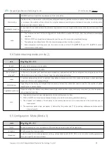
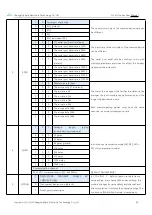
Page 25: ...uction remark 0 RSSI mode 0 0 0 The serial port is open closed wirelessly and cannot be transmitted The module outputs RSSI intensity values every 100ms serial port 1 Continuous transmission mode 0 0...
Page 26: ...the external interrupt function to capture the AUX change for mode switching This operation is very flexible and efficient designed exactly for the user s MCU to operate and can minimize the workload...
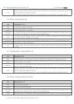
Page 27: ...ode the serial port baud rate and airspeed are independent and the sending and receiving parties can have different serial port baud rates but must have the same airspeed setting merit A very low airs...
Page 28: ...ios Used to wake up receivers in WOR state note In wake up mode the maximum transmit length of a single packet is 84 bytes excluding directed addresses and channels 6 7 Configuration Mode Mode 5 state...
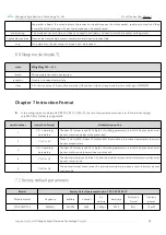
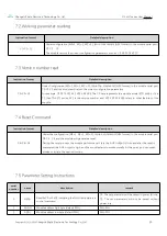
Page 29: ...ode 3 M0 1 M1 1 M2 0 the list of supported instructions is as follows when setting only 9600 8N1 format is supported serial number Instruction format Detailed description 1 C0 operating parameters The...
Page 30: ...is 71 then the E71 series XX1 is the version number and XX2 XX3 XX4 XX5 refers to other features of the module 7 4 Reset Command Instruction format Detailed description C4 C4 C4 Under the configurati...
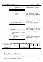
Page 31: ...rther the distance the stronger the anti interference performance and the longer the transmission time Both communicating parties must have the same over the air wireless transmission rate 0 0 0 The a...
Page 32: ...d according to the actual application Both parties to the communication must be on or off 0 Turn off the FEC 1 Open FEC default 2 IO drive mode This bit is used to enable the internal pull up resistor...
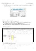
Page 33: ...s please contact the sales hotline 4000 330 990 9 1 Program Burning keywords Precautions Programming procedures The module is an SoC module with its own GPIO port and the program downloads using a CC...
Page 34: ...erence and if the situation permits appropriate isolation and shielding can be done Assuming that there are traces with large electromagnetic interference around the module high frequency digital high...
Page 35: ...at the humidity during installation and use should not be too high and some components are humidity sensitive devices If there is no special need it is not recommended to use it at too high or too low...
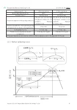
Page 36: ...the temperature indicated on the product s Moisture Sensitivity label The user must not exceed the temperature indicated on the product s Moisture Sensitivity label The time Tp within 5 C of the speci...
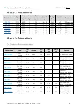
Page 37: ...ct model type Band Hz interface gain dBi height mm Feeder cm Features TX433 NP 4310 Flexible antenna 433M weld 2 0 43 10 Flexible FPC soft antenna TX433 JZ 5 Glue stick antenna 433M SMA J 2 0 52 Ultra...
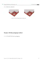
Page 38: ...Ltd E70 433T series User Manual Copyright 2012 2020Chengdu Ebyte Electronic Technology Co Ltd 37 14 2 Antenna selection Enable IPEX interface default Enable the stamp hole Chapter 15 Bulk packaging m...
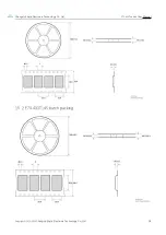
Page 39: ...Chengdu Ebyte Electronic Technology Co Ltd E70 433T series User Manual Copyright 2012 2020Chengdu Ebyte Electronic Technology Co Ltd 38 15 2 E70 433T14S batch packing...
Page 40: ...Chengdu Ebyte Electronic Technology Co Ltd E70 433T series User Manual Copyright 2012 2020Chengdu Ebyte Electronic Technology Co Ltd 39 15 3 E70 433T14S2 bulk packaging 15 4 E70 433MT14S bulk packing...
Page 41: ...on Notes Maintainers 1 0 2022 10 22 Initial release Hao About us Technical support support cdebyte com Documents and RF Setting download link https www cdebyte com Thank you for using Ebyte products P...