background image

Chengdu Ebyte Electronic Technology Co,;Ltd

E30-490T20D user manual

Copyright ©2012–2019

Chengdu Ebyte Electronic Technology Co,;Ltd

16

8. Hardware design

It is recommended to use a DC stabilized power supply. The power supply ripple factor is as small as possible, and
the module needs to be reliably grounded.

Please pay attention to the correct connection of the positive and negative poles of the power supply. Reverse
connection may cause permanent damage to the module

Please check the power supply to ensure it is within the recommended voltage otherwise when it exceeds the
maximum value the module will be permanently damaged

Please check the stability of the power supply, the voltage can not be fluctuated frequently

When designing the power supply circuit for the module, it is often recommended to reserve more than 30% of the
margin, so the whole machine is beneficial for long-term stable operation.

The module should be as far away as possible from the power supply, transformers, high-frequency wiring and other
parts with large electromagnetic interference.

High-frequency digital routing, high-frequency analog routing, and power routing must be avoided under the
module. If it is necessary to pass through the module, assume that the module is soldered to the Top Layer, and the
copper is spread on the Top Layer of the module contact part(well grounded), it must be close to the digital part of
the module and routed in the Bottom Layer

Assuming the module is soldered or placed over the Top Layer, it is wrong to randomly route over the Bottom Layer
or other layers, which will affect the module's spurs and receiving sensitivity to varying degrees

It is assumed that there are devices with large electromagnetic interference around the module that will greatly
affect the performance. It is recommended to keep them away from the module according to the strength of the
interference. If necessary, appropriate isolation and shielding can be done

Assume that there are traces with large electromagnetic interference (high-frequency digital, high-frequency analog,
power traces) around the module that will greatly affect the performance of the module. It is recommended to stay
away from the module according to the strength of the interference. If necessary, appropriate isolation and shielding
can be done.

If the communication line uses a 5V level, a 1k-5.1k resistor must be connected in series (not recommended, there is
still a risk of damage)

Try to stay away from some physical layers such as TTL protocol at 2.4GHz , for example: USB3.0

The mounting structure of antenna has a great influence on the performance of the module. It is necessary to ensure
that the antenna is exposed, preferably vertically upward. When the module is mounted inside the case, use a good
antenna extension cable to extend the antenna to the outside

The antenna must not be installed inside the metal case, which will cause the transmission distance to be greatly
weakened.

9 FAQ

9.1 Communication range is too short

The communication distance will be affected when obstacle exists.

Data lose rate will be affected by temperature, humidity and co-channel interference.

Summary of Contents for E30 Series

Page 1: ...E30 490T20D User Manual SI4438 490MHz 100mW DIP Wireless Module...

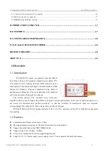
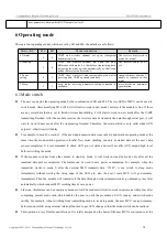
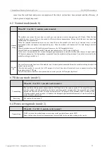
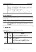
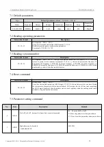
Page 2: ...FIXED TRANSMISSION 7 5 2 BROADCASTING TRANSMISSION 7 5 6 1 Indication of UART output 8 5 6 2 Indication of wireless transmitting 8 5 6 3 Configuration procedure of module 9 5 6 4 Notes for AUX 9 6 OP...

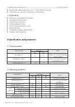
Page 3: ...action They are applicable in the industrial and living environment like a plant or indoors The module features FEC Forward Error Correction algorithm which ensure its high coding efficiency good corr...

Page 4: ...arameter 2 1 Limit parameter Main parameter Performance Notes Min Max Power supply V 0 5 2 Voltage over 5 2V will cause permanent damage to module Blocking power dBm 10 Chances of burn is slim when mo...

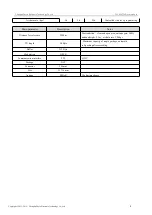
Page 5: ...ing Main parameter Description Notes Distance for reference 2500m Test condition clear and open area antenna gain 5dBi antenna height 2 5m air data rate 1 0kbps TX length 58 Byte Maximum capacity of s...

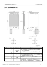
Page 6: ...M1 Input weak pull up Work with M0 to decide 4 working modes of module not suspended if not used could be grounded 3 RXD Input TTL UART inputs connects to external MCU PC TXD output pin Can be configu...

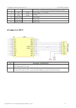
Page 7: ...d as push pull output suspending is allowed 6 VCC Input Power supply 2 3 5 5V DC 7 GND Input Ground 8 Fixed orifice Fixed orifice 9 Fixed orifice Fixed orifice 10 Fixed orifice Fixed orifice 4 Connect...

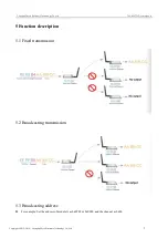
Page 8: ...r manual Copyright 2012 2019 Chengdu Ebyte Electronic Technology Co Ltd 7 5 Function description 5 1 Fixed transmission 5 2 Broadcasting transmission 5 3 Broadcasting address For example Set the addre...

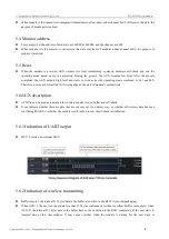
Page 9: ...o work as per the operating mode combined by M1 and M0 Therefore users need to wait the AUX rising edge as the start of module s normal work 5 6 AUX description AUX Pin can be used as indication for w...

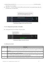
Page 10: ...rity should be given to the one with low level output which means if it meets each of any low level output condition AUX outputs low level if none of the low level condition is met AUX outputs high le...

Page 11: ...start to work in new mode after the transmitting finished Therefore the mode switch is only valid when AUX outputs 1 otherwise it will delay For example in mode 0 or mode 1 if the user inputs massive...

Page 12: ...ther 512 bytes continuously The data package transmitted from the module working in mode 0 can only be received by the module working in mode 0 or 1 Receivi ng The wireless receiving function of the m...

Page 13: ...e used for parameter setting It uses serial port 9600 8N1 to set module working parameters through specific instruction format pls refer to parameters setting for details Notes When the mode changes f...

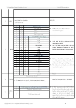
Page 14: ...32 xx yy the second bytes means frequency 32 here means the frequency is 433MHZ 38 means frequency is 470MHz 45 means frequency is 868MHz 44 means the frequency is 915 MHz 46 means the frequency is 17...

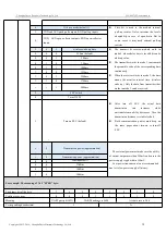
Page 15: ...1 0 57600 1 1 1 115200 2 1 0 Air data rate bps The lower the air data rate the longer the transmitting distance better anti interference performance and longer transmitting time The air data rate must...

Page 16: ...r that works in mode 1 can be received 0 0 0 250ms default 0 0 1 500ms 0 1 0 750ms 0 1 1 1000ms 1 0 0 1250ms 1 0 1 1500ms 1 1 0 1750ms 1 1 1 2000ms 2 FEC switch After turn off FEC the actual data tran...

Page 17: ...red or placed over the Top Layer it is wrong to randomly route over the Bottom Layer or other layers which will affect the module s spurs and receiving sensitivity to varying degrees It is assumed tha...

Page 18: ...re are taken when installing and using high frequency devices have electrostatic susceptibility Please ensure the humidity is within limited range some parts are sensitive to humidity Please avoid usi...

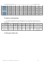
Page 19: ...5 1k 25k DIP 21 36 SMA K E30 433T20S SI4438 433M 20 2 1k 25k SMD 17 30 IPEX External Spring E30 433T20D SI4438 433M 20 2 1k 25k DIP 21 36 SMA K 12 Antenna recommendation The antenna is an important r...

Page 20: ...rsion huaa 1 20 2018 01 29 Type merging huaa 1 30 2018 10 17 New added type huaa 1 40 2020 7 10 Li About us Technical support support cdebyte com Documents and RF Setting download link www ebyte com T...

Reviews: