background image

Chengdu Ebyte Electronic Technology Co., Ltd.

E200-900A17S User Manual

Copyright ©2012–2021

Chengdu Ebyte Electronic Technology Co.,Ltd

14

Revision history

Version

Date

Description

Issued by

1.0

2020-06-16

Initial version

1.1

2020-07-21

Format correction

Ren

1.2

2022-09-06

Content correction

Hao

About us

Technical support:

[email protected]

Documents and RF Setting download link:

https://www.cdebyte.com

Thank you for using Ebyte products! Please contact us with any questions or suggestions: [email protected]
-------------------------------------------------------------------------------------------------
Official hotline:028-61399028
Web:

https://www.cdebyte.com

Address: , Building B5, Mould Industrial Park, 199# Xiqu Ave, High-tech Zone, Chengdu, 611731, Sichuan, China

Summary of Contents for E200-900A17S

Page 1: ...E200 900A17S User Manual 900MHz Wireless Audio Module ...

Page 2: ...LECTRIC PARAMETER 5 2 3 HARDWARE PARAMETER 6 3 SIZE AND PIN DEFINITION 6 4 RECOMMENDED CIRCUIT DIAGRAM 8 5 CHANNEL CODE VALUE TABLE 8 6 WORKING MODE 9 7 COMMAND AND FACTORY PARAMETER 9 7 1 COMMAND FORMAT 9 7 2 FACTORY DEFAULT PARAMETER 9 8 HARDWARE DESIGN 10 9 FAQ 11 9 1 COMMUNICATION RANGE IS TOO SHORT 11 9 2 MODULE IS EASY TO DAMAGE 11 9 3 POOR SOUND QUALITY 11 10 PRODUCTION GUIDANCE 12 10 1 REF...

Page 3: ...Ebyte Electronic Technology Co Ltd E200 900A17S User Manual Copyright 2012 2021 Chengdu Ebyte Electronic Technology Co Ltd 2 12 ANTENNA GUIDANCE 13 13 PACKAGE FOR BATCH ORDER 13 REVISION HISTORY 14 ABOUT US 14 ...

Page 4: ...oduction use modification or disclosure to third parties of this document or any part thereof without the express permission of EBYTE is strictly prohibited The information contained herein is provided as is and EBYTE assumes no liability for the use of the information No warranty either express or implied is given including but not limited with respect to the accuracy correctness reliability and ...

Page 5: ...n external amplifier and the audio output can directly drive 250mW 8ohm speakers The RF part provides a sensitivity of up to 98dBm which greatly improves the wireless distance 1 2 Features Supports one to multiple broadcast transmission Under ideal conditions the communication distance is up to 300m Control the working channel through the channel pin restart takes effect easy to use The master sla...

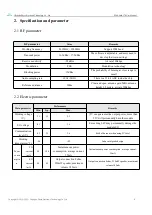
Page 6: ...de the chip Reference distance 300m Clear and open antenna gain 5dBi antenna height 2 5 meters air rate 500kbps 2 2 Electric parameter Main parameter Performance Remarks Min Typ Max Working voltage V 2 3 3 3 5 5 5V can guarantee the output power more than 5 5V will permanently burn the module I O voltage 0 3 3 6 Exceeding 3 6V may permanently damage the module I O Communication level V 0 3 3 3 3 6...

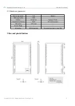
Page 7: ...onic Technology Co Ltd 6 2 3 Hardware parameter Hardware parameter Value Remarks Packaging method SMD Interface Stamp hole Spacing 1 27mm Communication Interface UART TTL level reserved Dimensions 16 26 mm Product Weight RF interface IPEX Stamp hole Equivalent impedance is about 50Ω 3 Size and pin definition ...

Page 8: ...N Debug control pin enter program programming mode for low level module can be floating when not using 26 CH3 Input Channel 3 combined with CH0 CH1 CH2 to select 16 working channels see the channel table for details 27 CH2 Input Channel 2 combined with CH0 CH1 CH2 to select 16 working channels see the channel table for details 28 CH1 Input Channel 1 combined with CH0 CH1 CH2 to select 16 working c...

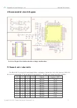
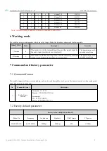
Page 9: ...rough different combinations of high and low levels of the four pins of CH0 CH3 The low level is represented by 0 and the high level is represented by 1 The frequency correspondence table is as follows CH3 CH2 CH1 CH0 Channel Frequency MHZ 0 0 0 0 Channel 0 863 275 0 0 0 1 Channel 1 863 79 0 0 1 0 Channel 2 864 295 0 0 1 1 Channel 3 864 795 0 1 0 0 Channel 4 868 115 0 1 0 1 Channel 5 903 205 0 1 1...

Page 10: ... audio input interface is sent wirelessly The transmission can be switched in real time RX mode 1 The module is in the receiving state and the wirelessly received signal is output through the audio output interface The transmission can be switched in real time 7 Command and factory parameter 7 1 Command format The module supports software version reading and can be read through the serial port in ...

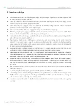
Page 11: ...lose to the digital part of the module and routed in the Bottom Layer Assuming the module is soldered or placed over the Top Layer it is wrong to randomly route over the Bottom Layer or other layers which will affect the module s spurs and receiving sensitivity to varying degrees It is assumed that there are devices with large electromagnetic interference around the module that will greatly affect...

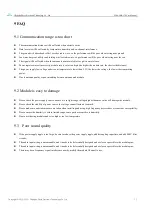
Page 12: ...ing power Due to antenna quality or poor matching between antenna and module 9 2 Module is easy to damage Please check the power supply source ensure it is in right range voltage higher than max value will damage the module Please check the stability of power source the voltage cannot fluctuate too much Please make sure antistatic measure are taken when installing and using high frequency devices ...

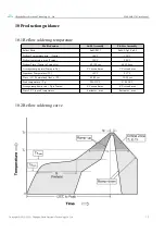
Page 13: ...n96 5 Ag3 Cu0 5 Preheat Temperature min Tsmin 100 150 Preheat temperature max Tsmax 150 200 Preheat Time Tsmin to Tsmax ts 60 120 sec 60 120 sec Average ramp up rate Tsmax to Tp 3 second max 3 second max Liquidous Temperature TL 183 217 Time tL Maintained Above TL 60 90 sec 30 90 sec Peak temperature Tp 220 235 230 250 Aveage ramp down rate Tp to Tsmax 6 second max 6 second max Time 25 to peak tem...

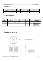
Page 14: ...mm Communication interface E200 470A17S 470 033M 512 273M 17 5 0 3 SMD 16 26 Analog TTL 12 Antenna guidance Model No Type Frequency Hz Interface Gain dBi Height mm Cable cm Function feature TX868 JZLW 5 Rubber antenna 868MHz IPEX 1 3 0 165mm Ultra short straight omnidirectional antenna TX915 JZLW 15 Rubber antenna 915MHz IPEX 1 3 0 165mm Ultra short straight omnidirectional antenna 13 Package for ...

Page 15: ... 21 Format correction Ren 1 2 2022 09 06 Content correction Hao About us Technical support support cdebyte com Documents and RF Setting download link https www cdebyte com Thank you for using Ebyte products Please contact us with any questions or suggestions info cdebyte com Official hotline 028 61399028 Web https www cdebyte com Address Building B5 Mould Industrial Park 199 Xiqu Ave High tech Zon...

Reviews: