


Chengdu Ebyte Electronic Technology Co.,Ltd
Copyright ©2012–2019
,
Chengdu Ebyte Electronic Technology Co.,Ltd
4-7
it a little.
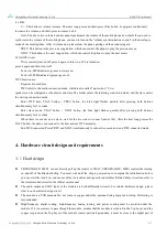
V +: This button is volume increase. There are long-press and short-press of the button. Long-press continuously
increases the volume, and short-press increases it a bit.
Note: The above two volume buttons cannot synchronize the volume of the mobile phone by default. If you need to
synchronize the volume of the mobile phone, you need to turn on the "volume synchronization control" in the developer
mode of the mobile phone. After it is turned on, please clear the phone pairing and then connect again.
PREV: This button is the previous song button, which can control the phone to play the previous music
NEXT: This button is the next song button, which can control the phone to play the next music,
H: On/Off circuit
If it is currently turned off, press it again to turn it on. If it is turned on,
press it again and then turn it off.
Power on, MFB indicator (green) is always on.
Power off, MFB indicator (green) goes out.
TWS function use:
Requires two modules.
TWS refers to the multi-connection mode, which is also called "pair-to-box". Two
speakers can be configured as the master and slave.The master enters the initiating connection mode, and the slave enters
the waiting connection mode.
Enter TWS host: PLAY PREV button, the blue light flashes quickly after pressing both buttons
simultaneously for 2 seconds
Enter slave mode: PLAY NEXT button, the blue light flashes quickly after pressing both buttons
simultaneously for 2 seconds
When there is a master and a slave, wait for the two sides to connect (about 10s). After the host long presses the
PALY button, the phone can connect to the host and use TWS normally.
End TWS connected: Press PREV and NEXT simultaneously for about two seconds to end TWS connected mode.
4. Hardware circuit design and requirements
4.1
Hard design
VREGENABLE
(
MFB
)
cannot directly pull up the resistor to VBAT, VREGENABLE
(
MFB
)
controls the turning
on and off of the Bluetooth chip. You must wait until the chip is powered on to complete the initialization before
you can start the turn it on, and cannot delay via resistors and capacitors(unstable). Related delay circuit can refer to
the recommended circuit in the official user manual.
The audio output and MIC input of the module are both differential circuits. For related hardware design, please
refer to our hardware design circuit.
The module is a PCB antenna. Do not route or copper under the antenna during layout and wiring. Hollowing is
recommended.
High-frequency digital routing, high-frequency analog routing, and power routing must be avoided under the
module. If it is necessary to pass through the module, assume that the module is soldered to the Top Layer, and the
copper is spread on the Top Layer of the module contact part(well grounded), it must be close to the digital part of


