12/14 MN05003004Z-EN
47
6 Creating a sample project
The following example aims to help you learn how to use the
easySoft CoDeSys software. You create a project by creating a
configuration and a program. You can then test out the project
after it has been downloaded.
The configuration is created in the easySoft CoDeSys configuration
editor. A distinction is made between local and central I/Os:
The local (digital) inputs and outputs are integral parts of the CPU
module, implemented on the power supply board. They are
already pre-configured in the configuration editor.
The central inputs/outputs are implemented in the signal modules,
which can be joined up via the module rack. Configure them to suit
the requirements of the application. The available XI/OC signal
modules can be used.
Connect appropriate CANopen fieldbus participants to the
CANopen interface.
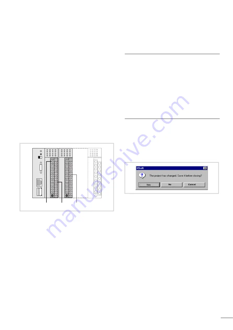
The basis for the configuration is the following hardware layout.
Task
Make a logical AND linkage of inputs I0.0 and I2.7 on the XC100.
The result of this logical operation should be presented at output
Q0.3.
The second step is to read in the inputs/generate the outputs,
using a CAN Master.
Activate the appropriate CAN libraries before linking the CAN
Master [VAR] module into the controller configuration. This
sequence will not take place automatically, but must be explicitly
carried out by the user.
Procedure
Setting up a target system
After starting easySoft CoDeSys, create a new file:
X
Select the menu item ‹File
r
New›.
X
Answer the query about saving the old project.
Select the target system. In the example, the system XC-CPU101-
C64K-8DI-6DO has been selected.
Figure 60: Hardware layout for the sample project
%IX0.0 %QX0.3 %IX2.7
Figure 61: Save old project?
Summary of Contents for XC-CPU101 Series
Page 18: ...II...
Page 22: ...12 14 MN05003004Z EN 4...
Page 42: ...12 14 MN05003004Z EN 24...
Page 64: ...12 14 MN05003004Z EN 46...
Page 88: ...12 14 MN05003004Z EN 70...


