


Data mapping of SmartWire
stations
29
07/09 MN03407002Z-EN
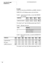
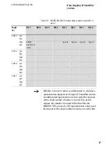
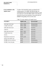
Data diagram
The MODBUS RTU gateway always outputs its data
according to the physical location of the SmartWire stations.
The first data bits within each register area are for the first
SmartWire station next to the MODBUS RTU gateway.
The following table provides an example with abbreviated
status data area 1 (register area 40007 to 40008).
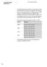
Number of SmartWire
stations
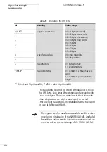
40143
2 bytes
binary diagram
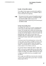
Watchdog timer (non-
retentive)
44097
2 bytes
Low byte:
Time = value × 10 ms
High byte: not assigned
Watchdog-Timer
(remanent)
44098
2 bytes
Low byte:
Time = value × 10 ms
High byte: not assigned
Designation
Register area
Data width:
Diagram
h
You can download a full detailed list of registers and their
content from
ftp://ftp.moeller.net/SMARTWIRE/English/
01_PRODUCT/04_AWB/Register_structure_SWIRE-GW-
MB
.
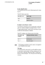
Summary of Contents for SWIRE-GW-MB
Page 14: ...10 07 09 MN03407002Z EN ...
Page 26: ...22 07 09 MN03407002Z EN ...
Page 30: ...26 07 09 MN03407002Z EN ...
Page 58: ...54 07 09 MN03407002Z EN ...
Page 63: ...Dimensions 59 07 09 MN03407002Z EN Dimensions M4 7 5 35 5 7 5 90 102 110 105 109 4 5 ...
Page 64: ...60 07 09 MN03407002Z EN ...