2 Installation
2.5 Connecting the power supply
SmartWire-DT Gateway EU5C-SWD-DP
01/13 MN120001Z-EN
www.eaton.eu
15
2.5 Connecting the power supply
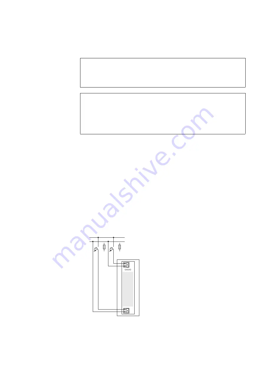
The gateway and the SmartWire-DT modules are powered via the POW ter-
minals. The Gateway uses the voltage at POW to generate the 15-V supply
voltage for the SmartWire-DT modules with a maximum output current of
0.7 A.
If loads or contactor modules are also connected via the SWD line, the 24-
VDC control voltage for the loads must be supplied in addition to the device
supply voltage. The AUX terminals are used for this purpose.
Take into account the total power consumption and the voltage drop in your
SWD line and, if necessary, include additional supply units, such as power
feeder modules, in your design. The SWD assist software program will pro-
vide support when you are carrying out the corresponding calculations. In
addition, it will automatically let you know if additional power supply modules
are required for your design.
The manual "SmartWire-DT The System", MN05006002Z-EN, contains
detailed calculation examples.
Figure 10:
Connection of power supply
DANGER
In safety-relevant applications the power supply providing
power to the SmartWire-DT system must feature a PELV power
supply unit (protective extra low voltage).
DANGER
The gateway has protection against polarity reversal for the 24-
V-DC-POW supply. If, however, the gateway is connected to a
grounded device, e.g., a computer, via the diagnostic interface,
the gateway may be destroyed if the polarity of the power sup-
ply is reversed!
24V
0V
AUX
24 V DC
0 V
POW
24V
0V
F1
F2


