background image

Series NRX Low Voltage Power 

(Air) Circuit Breakers User Manual

Instructions apply to:

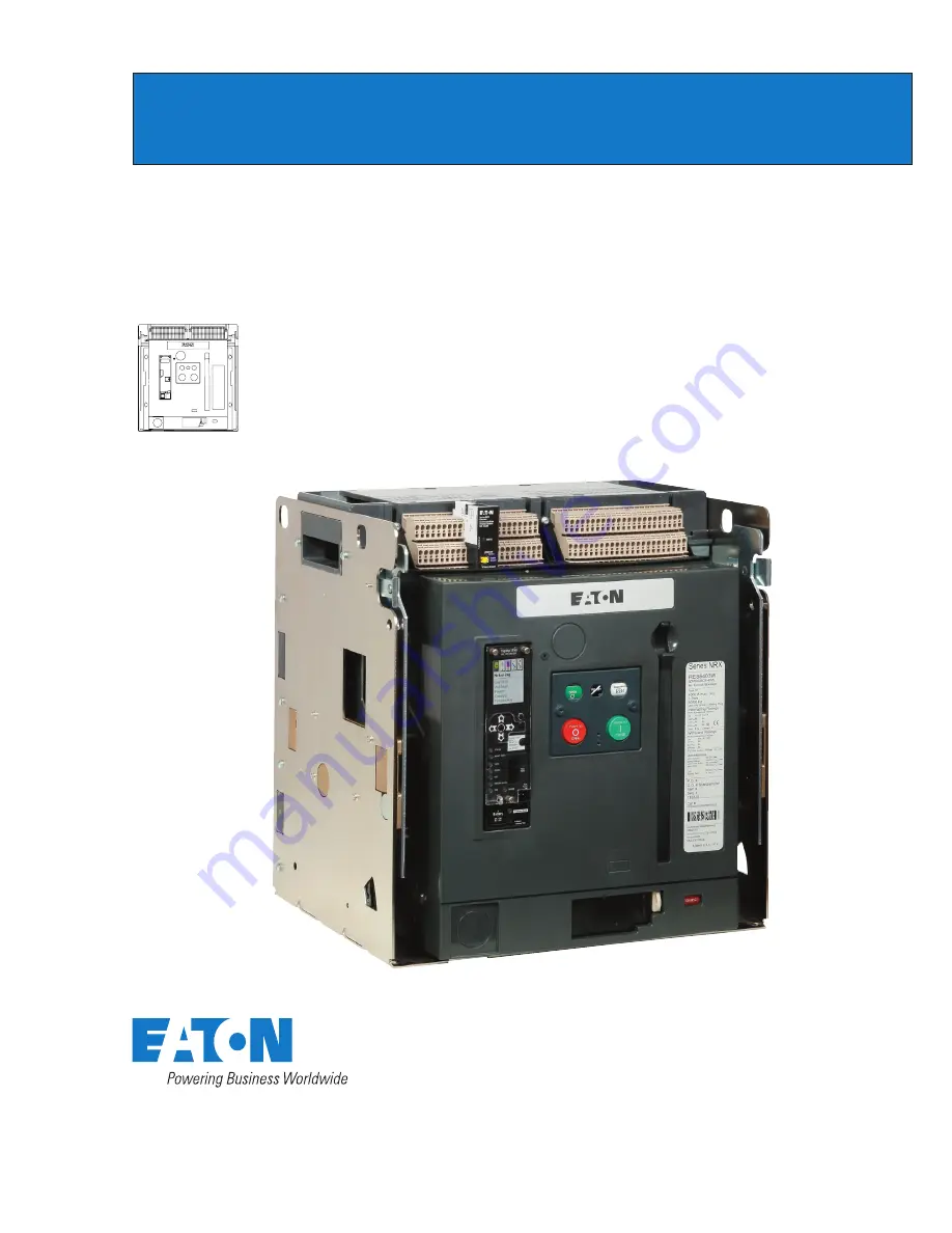
Series NRX, Type RF Frame 

IEC, IZMX40

4000 NRX RF DRAWOUT SUBTITLE IMAGE (12/15/2010)

effective July 2011         

Series NRX

Instructional Book 

MN01301003E

Typical Drawout Circuit 

Breaker and Cassette

Summary of Contents for Series NRX

Page 1: ...rcuit Breakers User Manual Instructions apply to Series NRX Type RF Frame IEC IZMX40 4000 NRX RF DRAWOUT SUBTITLE IMAGE 12 15 2010 effective July 2011 Series NRX Instructional Book MN01301003E Typical Drawout Circuit Breaker and Cassette ...

Page 2: ...re 1 Series NRX Nameplate Location 5 Figure 2 Series NRX Catalog Numbering System 6 Figure2a Series NRX Type RF Frame Cassette Catalog Numbering System 8 Figure 3 Typical NRX Drawout Circuit Breaker 9 Figure 4 Typical NRX Drawout Cassette 10 Figure 5 Typical NRX Fixed Circuit Breaker 11 Figure 6 Typical NRX Drawout Circuit Breaker Front Cover 12 Figure 7 Step 1 13 Figure 8 Step 3 13 Figure 9 Step ...

Page 3: ...ut Cassette Top Side Views with 4000A Vertical Bus Adapters 34 Figure 39 3 Pole Drawout Cassette Front View Door Cutout Details 35 Figure 40 4 Pole Drawout Cassette Rear Bottom Views 36 Figure 41 4 Pole Drawout Cassette CONNECTED TEST Positions 37 Figure 42 4 Pole Drawout Cassette DISCONNECT WITHDRAWN 38 Figure 43 4 Pole Drawout Cassette Top Side Views with 800 3200A Horizontal Bus Adapters 39 Fig...

Page 4: ...ent the following practices must be followed 1 Only qualified electrical personnel familiar with the equipment its operation and the associated hazards should be permitted to work on install or operate the equipment 2 Always be certain that the primary and secondary circuits are de energized or the circuit breaker is open and removed to a safe work location before attempting any maintenance 3 For ...

Page 5: ... OPERATION OUTSIDE OF THESE RATINGS COULD RESULT IN DEATH BODILY INJURY OR PROPERTY DAMAGE V V V V V Frame Type Product Coding Applicable Rating Plug Group Standards Poles Max rated current of the frame Max rated voltage and frequency Rated operational voltage Rated short circuit breaker capacity service Rated short circuit breaker capacity ultimate Rated short time withstand Third party certifica...

Page 6: ...c IEC SC 105kA at 440Vac IEC Position 5 6 Rated Operational Current 07 630A Frame 08 800A Frame 10 1000A Frame 13 1250A Frame 16 1600A Frame 20 2000A Frame 25 2500A Frame 32 3200A Frame 40 4000A Frame Position 7 Poles Phasing 3 3 Pole ABC 4 4 Pole NABC Position 8 Mounting Config W Drawout B Fixed Electronic Trip Unit Selection Protection ZSI ARMS Position 9 10 No Protection Switch Disconnector Non...

Page 7: ... Trip Indicator 2 Form C Per Breaker Options 24V RR E Interlock Trip Indicator 2 Form C Per Breaker Options 120V RR F Interlock Trip Indicator 2 Form C Per Breaker Options 240V RR 1 None None Full Compliment No RR 2 Trip Indicator None Full Compliment No RR 3 Trip Indicator 2 Form C Full Compliment No RR 4 Interlock Trip Indicator No OTS Full Compliment No RR J Interlock Trip Indicator No OTS Full...

Page 8: ... Breaker Overview Figures 3 6 highlight the main components that make up a Series NRX breaker Drawout breaker and cassette A drawout circuit breaker is used in combination with a drawout cassette Figures 3 and 4 Mounted on the drawout breaker are the primary finger clusters and levering mechanism These components are located on the breaker to allow users easy access when performing product inspect...

Page 9: ...on com 1 Arc Chute Cover 2 Front Cover 3 Drawout Wheels 4 Lifting Handle 5 Plug Connector for Secondary Contacts 6 Primary Finger Cluster 7 Phase Barriers optional 8 Levering Mechanism 9 On Board Lev in Tool 1 4 3 2 1 5 4 3 6 7 8 9 8 Figure 3 Typical NRX Drawout Circuit Breaker Note N Refer to Figure 6 for more visual details of front cover ...

Page 10: ...Rail shown in extended and locked position 2 Secondary Connectors 3 Lifting Handle 4 Interlock Plate Pins 5 Grounding earthing Bar 6 Gas Ventilation Opening 7 Stationary Primary Contacts 8 Safety Shutters optional 9 Primary Terminal Pad 10 Barrier optional 11 Secondary Wiring Point Identification 10 5 1 3 2 6 1 7 8 4 3 1 6 9 6 11 Figure 4 Typical NRX Drawout Cassette ...

Page 11: ...l EATON CORPORATION www eaton com 1 Front Cover 2 Secondary Contacts 3 Arc Chute Cover 4 Lifting Handle 5 Primary Terminal Pad 6 Secondary Point Identification 7 Installation Mounting Feet 3 4 2 1 4 5 3 6 7 7 Figure 5 Typical NRX Fixed Circuit Breaker Note N Refer to Figure 6 for more visual details of front cover ...

Page 12: ...Padlock Drawout Only 6 Levering Access Door Drawout Only 7 Levering Key Lock Optional Drawout Only 8 Frame Rating Module 9 Rating Plug 10 Test Port 11 Trip Unit 12 Pop out Trip Indicator Optional 13 Breaker Key Lock Optional 14 Contact Status 15 Ready to close Status Flag 16 Mechanism Spring Status 17 Manual OFF 18 Manual ON 19 Padlock Pushbutton Cover Mounting Holes 2 9 7 11 17 8 10 6 12 4 1 3 13...

Page 13: ...ngle at top of indicator is partially full or totally full of blue beads Transport was not in keeping with instructions breaker container was tilted or overturned Check breaker closely for damage Triangle at top of indicator has no blue beads in it Breaker container was not tilted or overturned during transport Triangle Blue Beads When ready to inspect and or install a Series NRX circuit breaker p...

Page 14: ...tional Book MN01301003E Effective July 2011 Table 2 Suggested Lifting Procedures and Precautions When using an appropriate overhead lifting device attach the lifting harness in the locations as shown below that best fits the circumstance Upright Cassette Breaker in Cassette Cassette Front Up Breaker Only ...

Page 15: ...THE CASSETTE TIPPING FORWARD RESULTING IN EQUIPMENT DAMAGE AND OR BODILY INJURY Step 6 All circuit breakers once removed from their shipping containers should be visually inspected for any obvious damage Check to make sure that the installed trip unit and nameplate information match the equipment as ordered All circuit breakers should be operated as described in Section 3 prior to being put into s...

Page 16: ...GE AND OR BODILY INJURY To install the drawout circuit breaker proceed first with the following four steps Step 1 Press the extension rail spring away from the extension rail until the retaining pin is fully released Each drawout rail is provided with a curved cutout to accommodate a gloved hand Extension Rail Spring Figure 10 Step 1 Step 2 Lower both rails down into their extended and locked posi...

Page 17: ...n in the rejection plates on both the circuit breaker and cassette A rejection pin installation kit including the instruction leaflet IL01301006E is supplied by the factory for this purpose WARNING NEVER ATTEMPT TO DISABLE ANY INTERLOCKS DOING SO COULD RESULT IN AN ELECTRICAL FAULT THAT COULD RESULT IN DEATH BODILY INJURY AND OR EQUIPMENT DAMAGE Drawout circuit breaker positioning Series NRX drawo...

Page 18: ...SCONNECT Figure 15 Step 2 If the indicator window indicates anything other than DISCONNECT use the breaker s on board tool racking tool to get the circuit breaker in the proper levering position Insert the levering tool into its compatible front accessible fitting and rotate it counterclockwise until DISCONNECT is indicated in the window An audible click may be heard This is the levering in s dete...

Page 19: ...out rails IMPORTANT THE CIRCUIT BREAKER MECHANISM IS INTERLOCKED SUCH THAT CHARGED CLOSING SPRINGS ARE AUTOMATICALLY DISCHARGED IF THE CIRCUIT BREAKER IS LEVERED INTO OR OUT OF THE CELL DISCHARGE TAKES PLACE BETWEEN THE DISCONNECT AND TEST POSITIONS Operating mechanism The Series NRX operating mechanism is a two stage stored energy trip free mechanism Energy is stored for a closing operation with ...

Page 20: ...of an electrical operator The springs can however be charged manually as just described in the last section Electrically operated circuit breakers can also be manually closed and opened through the use of the front mounted ON and OFF buttons An electrically operated circuit breaker can be equipped with an optional spring release closing coil to close the circuit breaker remotely The breaker can al...

Page 21: ... four parts of the tripping system are discussed here in general For detailed information pertaining to the different available trip unit models refer to IL01301051E Digitrip 520 or IL01301064E Digitrip 1150 which are dedicated to the trip units and are available on Eaton s web site Microprocessor based trip unit Series NRX circuit breakers use any one of a family of Digitrip RMS trip units whose ...

Page 22: ...aneous trip feature The overall dimensions and the capability of mounting most accessory items are maintained Non automatic breakers are tested in keeping with IEC 60947 2 requirements ST1 1 2 ST2 UV1 3 4 UV2 OT1C 5 6 OT1M OT1B 7 8 OT2B OT2C 9 10 OT2M ALMC 11 12 ALM1 N1 15 16 N2 G1 17 18 G2 SGF2 19 20 SGF1 24V 21 22 AGND CMM1 23 24 CMM2 CMM3 25 26 CMM4 ZOUT 27 28 ZCOM ARMS2 33 34 ARMS1 35 36 37 38...

Page 23: ...7FCB01 with the odd assigned numbers having the coded rib feature on the black plug Fig ure 28 Note that the connector plug must be oriented as shown in Figure 28 before making the connection General wiring notes 1 Each contact block on the Secondary Terminal Block consists of two contacts Figure 27 A possible 46 terminal blocks will provide 92 contact points for the type RF frame Fixed Terminal B...

Page 24: ...riety of accessory devices are available for use with Series NRX circuit breakers Unless otherwise stated they are all considered optional devices in the sense that they are not provided as standard on a manually operated circuit breaker Available accessories are discussed in general terms For more detailed information and or installation instructions refer to individual instruction leaflets dedic...

Page 25: ...witch combinations only Other internal electrical devices There are three types of internally mounted electrical devices Spring release Latch check switch Motor operator Spring release SR The spring release closing coil remotely closes the circuit breaker when the coil is energized by a voltage input When the spring release is used in conjunction with a latch check switch the closing spring must b...

Page 26: ...tch bell alarm discussed later in this section that operates off the position of the mechanical trip indicator is also available Operations counter The operations counter is a mechanical device used to provide a record of the number of circuit operations It can be viewed through the breaker s front cover Figure 6 Off key lock The off key lock secures the circuit breaker in the OFF position It can ...

Page 27: ...RF IL for Pushbutton Cover Kit IL01301041E NF IL for Cassette Cell Switch IL01301043E NF IL for Draw out Cassette IP20 Safety Shutters IL01301044E RF IL for Neutral Current Sensor IL01301046E RF IL for Cassette Extension Rails IL01301047E RF IL for Breaker and Cassette Interphase Barriers IL01301048E RF IL for CES Key Lock IL01301049E NF and RF IL for Castell Key Lock IL01301050E NF and RF IL for ...

Page 28: ...E DETAIL A 17 96 456 2 4X Ø 35 9 35 9 43 11 2X 6 90 175 4 4 53 115 2X 3 82 97 4 72 119 9 5 20 132 1 4X Ø 38 9 6 4 53 115 43 11 16 77 425 8 35 9 5 13 103 2 3 85 97 8 5 25 133 4 4X MOUNTING LOCATIONS OF HOLE PATTERN DETAIL A Ø M8 X 1 25 TAPPED 0 35 IN MAX THREAD DEPTH FROM COPPER SURFACE 3X 15 14 384 6 16 77 425 8 6x Mounting Holes Must Use Reduced Head Height Hardware at These Locations 1 34 34 1 3...

Page 29: ...ual EATON CORPORATION www eaton com 13 62 346 73 18 4 14 93 379 2 2 17 55 1 58 14 8 Test Position 14 48 367 8 5 84 148 4 86 21 9 Connected Position 1 00 25 4 36 9 1 14 25 361 8 16 4 1 5 84 148 4 16 4 85 Travel 30 FreeTravel Figure 33 Three Pole Drawout Cassette Side Views CONNECTED and TEST Positions in Inches mm ...

Page 30: ... EATON CORPORATION www eaton com Instructional Book MN01301003E Effective July 2011 12 55 318 7 14 06 357 Disconnected Position Withdrawn Position 2 87 72 9 1 28 32 6 Figure 34 Three Pole Drawout Cassette Side Views DISCONNECTED and WITHDRAWN Positions in Inches mm ...

Page 31: ...l EATON CORPORATION www eaton com C L C L C L 57 14 5 1 06 27 1 02 26 ø 44 11 2 98 25 4 53 115 Optional Barrier 5 65 143 5 79 20 5 20 132 1 4 72 119 9 3x 2 99 76 3 85 97 9 4 53 115 6 06 154 4 53 115 Bus Bus Bus Figure 35 Three Pole Drawout Cassette Top Side Views with 800 3200A Horizontal Bus Adapters in Inches mm ...

Page 32: ...l Book MN01301003E Effective July 2011 4 53 115 57 14 5 1 06 27 1 02 26 ø 44 11 2 Bus 79 20 4 53 115 3 85 97 9 6 06 154 4 53 115 98 25 2x 2 99 76 4 72 119 9 5 65 143 5 Bus Optional Barrier 5 20 132 1 C L C L Figure 36 Three Pole Drawout Cassette Top Side Views with 800 3200A Vertical Bus Adapters in Inches mm ...

Page 33: ...TON CORPORATION www eaton com 57 14 5 1 06 27 1 02 26 ø 44 11 2 98 25 5 91 150 Optional Barrier 79 20 5 20 132 1 4 72 119 9 2x 4 62 117 5 2 48 62 9 5 91 150 6 06 154 4 53 115 Bus Bus Bus 3 94 100 5 65 143 5 C L C L C L Figure 37 Three Pole Drawout Cassette Top Side Views with 4000A Horizontal Bus Adapters in Inches mm ...

Page 34: ...al Book MN01301003E Effective July 2011 Figure 38 C L C L 57 14 5 1 06 27 1 02 26 ø 44 11 2 Bus 79 20 4 53 115 3 85 97 9 6 06 154 4 53 115 98 25 2x 4 62 117 5 3 34 84 8 5 65 143 5 Bus Optional Barrier 7 96 202 1 4 53 115 Three Pole Drawout Cassette Top Side Views with 4000A Vertical Bus Adapters in Inches mm ...

Page 35: ...51 393 9 16x ø 200 5 08 07 1 8 Cassette Sheet Metal 4 00 101 6 16 72 424 8 4 00 101 6 4 00 101 6 4 00 101 6 1 82 46 3 Cassette Sheet Metal 4 00 101 6 4 00 101 6 Cassette Sheet Metal 2 38 60 5 54 13 7 12 58 319 5 6 90 175 4 2 84 72 1 ø 44 11 2 See Figure 32 for Cassette Mounting Locations 15 72 399 4 15 09 383 3 Figure 39 Three Pole Drawout Cassette Front View Door Cutout Details in Inches mm ...

Page 36: ...21 29 540 9 OF HOLE PATTERN 35 9 4 72 119 9 DETAIL A 5 20 132 Ø M8X 1 25TAPPED 0 35 IN MAX THREAD DEPTH FROM COPPER SURFACE 21 29 540 85 1 34 34 4 53 115 3 85 97 8 5 13 130 2 19 67 499 6 5 25 133 4 43 11 21 29 540 8 4X Ø 35 Ø 9 35 9 6X MOUNTING HOLES MUST USE REDUCED HEAD HEIGHT HARDWARE ATTHESE LOCATIONS 4 53 115 4 53 115 2X 3 82 97 2X 6 90 175 3 17 96 456 2 Figure 40 Four Pole Drawout Cassette R...

Page 37: ...al EATON CORPORATION www eaton com 5 84 148 4 13 62 346 58 14 8 14 25 361 8 73 18 4 TEST POSITION 86 21 9 5 84 142 4 CONNECTED POSITION 14 48 367 8 1 00 25 4 36 9 1 14 93 379 2 16 4 1 85ºTRAVEL 30º FREETRAVEL 16 4 1 2 17 55 1 Figure 41 Four Pole Drawout Cassette Side Views CONNECTED and TEST Positions in Inches mm ...

Page 38: ...EATON CORPORATION www eaton com Instructional Book MN01301003E Effective July 2011 DISCONNECTED POSITION 2 87 72 9 14 06 357 12 55 318 7 1 28 32 6 WITHDRAWN POSITION Figure 42 Four Pole Drawout Cassette Side Views DISCONNECTED and WITHDRAWN Positions in Inches and mm ...

Page 39: ...eaton com Figure 43 1 06 27 57 14 5 79 20 5 20 132 1 98 25 Ø 44 Ø 11 2 1 02 26 4 72 119 9 BUS 4X 2 99 76 3X OPTIONAL BARRIER 3 BUS BUS 4 53 115 6 06 153 5 65 143 5 OPTIONAL BARRIER 3 85 97 9 4 53 115 4 53 115 4 53 115 4 53 115 C L C L C L BUS C L Four Pole Drawout Cassette Top Side Views with 800 3200A Horizontal Bus Adapters in Inches mm ...

Page 40: ...ffective July 2011 Figure 44 4 53 115 79 20 5 20 132 1 3X OPTIONAL BARRIERS 4 72 119 9 57 14 5 1 06 27 Ø 44 Ø11 2 OPTIONAL BARRIER 1 02 26 98 25 2X 2 99 76 5 65 143 5 BUS BUS C L C L 4 53 115 3 85 97 9 4 53 115 4 53 115 4 53 115 6 06 153 9 Four Pole Drawout Cassette Top Side Views with 800 3200A Vertical Bus Adapters in Inches mm ...

Page 41: ... com 1 06 27 57 14 5 98 25 Ø 44 Ø11 2 1 02 26 5 65 143 5 5 20 132 6 06 153 9 4 72 119 9 3X OPTIONAL BARRIERS 4 53 115 4 53 115 OPTIONAL BARRIER 4 53 115 2X 3 94 100 2X 4 62 117 5 BUS C L BUS C L BUS C L BUS C L 5 91 150 5 91 150 2 48 62 9 79 20 Figure 45 Four Pole Drawout Cassette Top Side Views with 4000A Horizontal Bus Adapters in Inches mm ...

Page 42: ...Effective July 2011 79 20 98 25 7 96 202 1 1 06 27 OPTIONAL BARRIER 1 02 26 57 14 5 ø 44 ø11 2 5 65 143 5 3X OPTIONAL BARRIERS BUS C L BUS C L 4 53 115 4 53 115 3 85 97 9 6 06 153 9 4 53 115 4 53 115 3 34 84 8 2X 4 62 117 5 4 53 115 Figure 46 Four Pole Drawout Cassette Top Side Views with 4000A Vertical Bus Adapters in Inches mm ...

Page 43: ...ET METAL 07 1 8 4 00 101 6 4 00 101 6 CASSETTE SHEET METAL CASSETTE SHEET METAL 1 82 46 3 54 13 7 2 38 60 5 2 84 72 1 Ø 44 Ø11 2 SEE FIGURE 40 FOR CASSETTE MOUNTING LOCATIONS 15 14 384 5 14 08 357 7 15 51 393 9 4 00 101 6 4 00 101 6 16 72 424 8 4 00 101 6 4 00 101 6 20 25 514 4 19 62 498 3 12 58 319 5 6 90 175 4 Figure 47 Four Pole Drawout Cassette Front View Door Cutout Details in Inches mm ...

Page 44: ...on and lubrication after the number of operations listed in Table 6 This should also be conducted at the end of the first six months of service if the number of operations has not been reached Table 6 Inspection Frequency Breaker Frame Size Interval Cycles 1 800A and below 1750 Between 800 and 4000A 500 1 Cycle 1 no load open close operation After the first inspection inspect at least once a year ...

Page 45: ...ened or closed as indicated by the indicator flags on the front of the breaker Figure 6 Step 1 Charge mechanism springs using charging handle or motor operator Step 2 Close breaker by applying rated voltage to the spring release accessory Step 3 Charge mechanism springs using either charging handle or motor operator If using motor operator disconnect power to motor prevent automatic recharging Ste...

Page 46: ...NT DAMAGE BODILY INJURY OR EVEN DEATH Primary contact inspection With the arc chutes removed visually inspect each primary contact structure for signs of wear and or damage with the circuit breaker open Series NRX primary contacts carrier assemblies cannot be replaced Contact Eaton for additional information Miscellaneous modifications and or changes The topics discussed here cover additional acti...

Page 47: ...not be opened locally OPEN pushbutton locked Remove lock Faulty mechanism or main contacts welded Contact Eaton Circuit breaker makes no attempt to close with either local manual or remote controls springs do not discharge Closing spring not fully charged check SPRING CHARGED indicator Charge spring manually check voltage to electrical operator replace operator if faulty If equipped with undervolt...

Page 48: ...outlined in appropriate Eaton selling policies or other contractual agreement between Eaton and the purchaser THERE ARE NO UNDERSTANDINGS AGREEMENTS WARRANTIES EXPRESSED OR IMPLIED INCLUDING WARRANTIES OF FITNESS FOR A PARTICULAR PURPOSE OR MERCHANTABILITY OTHER THAN THOSE SPECIFICALLY SET OUT IN ANY EXISTING CONTRACT BETWEEN THE PARTIES ANY SUCH CONTRACT STATES THE ENTIRE OBLIGATION OF EATON THE ...

Reviews: