3 Installation
3.6 Electrical Installation
66
DC1-S…20…, DC1-S…OE1 Variable Frequency Drives
05/21 MN040058EN
www.eaton.com
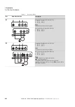
3.6.1.1 Terminals in power section for units with IP20 degree of protection
Table 6:
Terminals (IP20)
Size
Connection terminals
Description
FS1
Connection with single-phase supply voltage:
• DC1-S1… (115 V)
• DC1-S2… (230 V)
Hint:
Connection to terminal L3 not permissible!
Motor connection for single-phase AC motor:
• DC1-S1… (115 V)
• DC1-S2… (230 V)
FS2
Connection with single-phase supply voltage:
• DC1-S1… (115 V)
• DC1-S2… (230 V)
Hint:
Connection to terminal L3 not permissible!
DC-
: Negative DC link connection if using an external DC power supply
or DC link coupling.
The terminal’s plastic cover can be removed if necessary.
Motor connection for single-phase AC motor:
• DC1-S1… (115 V)
• DC1-S2… (230 V)
Hint:
DC+
: Positive DC link connection if using an external DC power supply,
DC link coupling, or braking chopper.
The terminal’s plastic cover can be removed if necessary.
BR
: Terminal for brake resistor (braking chopper output).
The terminal’s plastic cover can be removed if necessary.
L1/L
L2/N
L3
⏚
L
N
PE
U
V
W
⏚
PES
M
DC-
L1/L
L2/N
L3
⏚
L
N
PE
PES
DC+
BR
U
V
W
⏚
R
B
M
Summary of Contents for PowerXL
Page 4: ......


