background image

3 Installation

3.5 EMC installation

DC1-S…20…, DC1-S…OE1 Variable Frequency Drives

05/21 MN040058EN

www.eaton.com

61

3.5.5 EMC cable brackets

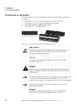
Frame-size-specific DX-EMC-MNT-… cable brackets can be used to easily 
route and secure cables in the connection area of a DC1-S… variable 
frequency drive with a frame size of FS1 or FS2 and an IP20 degree of 
protection. These cable brackets are mounted on the variable frequency 
drive’s mains connection side (DX-EMC-MNT-…

N

) and motor side 

(DX-EMC-MNT-…

M

) using the corresponding mounting holes, and are then 

connected to the drive’s earthing 

.

The cable brackets’ integrated hole pattern (M4 screw tread) makes it 
possible to secure the cables being connected and relieve any strain on them 
by using the corresponding gland plates. It also makes it possible to have a 
good 360° EMC connection (PES) in the case of screened cables.

These cable brackets are made of galvanized sheet steel.

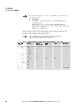
Table 5:

Cable brackets

Figure 35: DX-EMC-MNT-...

N

 (left), net and 

DX-EMC-MNT-...

M

 (right), motor, cable brackets

Cable bracket

Size DC1-S… in 
IP20

gland plates

Quantity

designation

DX-EMC-MNT-1N

FS1

1

Mains connection

DX-EMC-MNT-1M

FS1

2

Control cables, motor connection

DX-EMC-MNT-2N

FS2

1

Mains connection

DX-EMC-MNT-2M

FS2

3

Control cables, motor connection, 
external braking resistance

We recommend connecting the DX-EMC-MNT-… cable 
brackets to the variable frequency drive before installing it.

For more information and technical data on DX-EMC-MNT-… 
EMC cable brackets, please refer to instruction leaflet 
IL040010ZU.

Summary of Contents for PowerXL

Page 1: ...Manual PowerXL Titel DC1 S 20 DC1 S OE1 Variable Frequency Drives for single phase AC motors Installation and Parameter Manual 05 21 MN040058EN...

Page 2: ...Drives Technical Resource Center Voice 877 ETN CARE 386 2273 option 2 option 6 8 00 a m 5 00 p m Central Time U S UTC 6 email TRCDrives Eaton com www eaton com drives Original operating manual The Ger...

Page 3: ...ation system may cause damage to persons or property external measures must be implemented to ensure a safe operating state in the event of a fault or malfunction for example by means of separate limi...

Page 4: ......

Page 5: ...g the Delivery 11 1 4 Rated operational data 12 1 4 1 Rated operational data on the nameplate 12 1 4 2 Key to part numbers 14 1 4 3 Features 15 1 5 Description 17 1 5 1 IP20 degree of protection 17 1...

Page 6: ...motors 43 2 9 6 Three phase motors run from a single phase supply Steinmetz connection 44 2 9 7 Motor Selection 45 2 9 8 Connecting EX motors 45 3 Installation 47 3 1 Introduction 47 3 2 Mounting pos...

Page 7: ...r commissioning 109 5 4 Operational hazard warnings 110 5 5 Commissioning with control signal terminals default settings 112 5 5 1 Starting single phase motors 113 5 5 2 Start Up 114 5 6 Commissioning...

Page 8: ...155 6 7 3 Acknowledge error message RESET 155 6 7 4 Fault log 155 7 Technical Data 157 7 1 General rated operational data 157 7 2 Specific rated operational data 161 7 2 1 DC1 S1 device series 162 7...

Page 9: ...at can be used to modify the DC1 S variable frequency drive according to your specific needs will be listed where applicable 0 1 Target group This manual MN040058EN is intended for engineers and elect...

Page 10: ...light injury WARNING Warns of the possibility of hazardous situations that could result in serious injury or even death DANGER Warns of hazardous situations that result in serious injury or death Indi...

Page 11: ...rical Kundensupport DownloadCenter index htm dec Decimal base 10 numeral system DS Default settings EMC Electromagnetic compatibility FE Functional earth FS Frame Size FWD Forward run clockwise rotati...

Page 12: ...10 The rated mains voltage operational data is always based on mains frequencies of 50 60 Hz within a range of 48 to 62 Hz 0 6 Units of measurement Every physical dimension included in this manual us...

Page 13: ...20 For distributed local installations there are two frame sizes covering an output range of 0 37 with 115 V to 1 1 kW with 230 V and featuring a degree of protection of IP66 These models come in two...

Page 14: ...egree of protection IP20 a DC1 S variable frequency drive b Extern radio interference suppression filter DX EMC12 c Main choke DX LN1 d DX BR braking resistance e DXC EXT expansion module f DX NET SWD...

Page 15: ...d device Open the packaging with adequate tools and inspect the contents immediately after receipt in order to ensure that they are complete and undamaged The packaging must contain the following part...

Page 16: ...data on the nameplate The device specific rated operational data of the DC1 S variable frequency drive is listed on the nameplate of the device Figure 4 Nameplate location The nameplate on top namepl...

Page 17: ...boards E1 Expansion version 1 Input Rated operational data of mains connection Single phase AC voltage Ue 1 AC Voltage 110 150 V Frequency 50 60 Hz Input phase current 9 3 A Output Load side motor ra...

Page 18: ...nality enhancement version 1 C Additional PCB protection coated board Degree of protection 20 IP20 NEMA 0 66 IP66 NEMA 4X 6S IP66 with switch NEMA 4X switched Display unit display A LED display Brake...

Page 19: ...Display operating unit Local controls Radio interference suppression filter Degree of protection Construction size Brake chopper Ie P1 115 V 50 Hz P2 110 115 V 60 Hz A kW HP DC1 S17D0NN A20CE1 7 0 37...

Page 20: ...E1 4 33 0 37 0 5 LED IP66 FS1 DC1 S24D3NN A6SCE1 4 33 0 37 0 5 LED IP66 FS1 DC1 S24D3FN A6SCE1 4 33 0 37 0 5 LED IP66 FS1 DC1 S27D0NN A20CE1 7 0 75 1 LED IP20 FS1 DC1 S27D0FN A20CE1 7 0 75 1 LED IP20...

Page 21: ...1 S variable frequency drives with an IP20 degree of protection and a size of FS1 Figure 6 DC1 S description FS1 IP20 a Fixing holes screw fastening b Connection terminals in power section mains side...

Page 22: ...escription IP66 a Local controls with connection DC1 S A6SCE1 only b Keypad with 5 control buttons and LED display c Control terminal plug in d Connection terminals in power section e Nameplate f Fixi...

Page 23: ...se mains connection rated operating voltage 115 V ULN 1 110 115 V 10 50 60 Hz Ie 7 11 A Motor 0 37 0 55 kW 115 V 50 Hz 1 2 3 4 HP 115 V 60 Hz DC1 S2 Single phase mains connection rated operating volta...

Page 24: ...allation with IP66 degree of protection Example based on figure 9 Mains voltage 1 230 V 50 Hz Rated operational current 5 1 A Control panel installation IP20 degree of protection Ambient air temperatu...

Page 25: ...e drive will be run outside these conditions Derating for ambient temperature Derating for installation altitude Derating for switching frequency Enclosure degree of protection Maximum permissible amb...

Page 26: ...iable frequency drive s permissible continuous rated operational current of 3 58 A is lower than the motor s required rated operational current 5 A b Selected variable frequency drive DC1 S2011FB A6SC...

Page 27: ...the European Union s Low Voltage and EMC Directives Directives 2014 35 EU 2014 30 EU and ROHS 2011 65 EU when used in their typical drive configuration In the described system configurations DC1 S var...

Page 28: ...itable ambient conditions must be ensured at the site of storage Storage temperature 40 60 C Relative average air humidity 95 non condensing EN 50178 To prevent damage to the variable frequency drive...

Page 29: ...i e no start signal After this the DC voltage must be set to the magnitudes for the corresponding DC link voltage UDC 1 41 x Ue and applied for one hour at least regeneration time DC1 S1 about 162 V D...

Page 30: ...1 Device series DC1 S 1 13 Service and warranty 26 DC1 S 20 DC1 S OE1 Variable Frequency Drives 05 21 MN040058EN www eaton com...

Page 31: ...in your project planning It contains instructions that must be followed when determining which device to use with which rated motor output as well as when selecting protection devices and switchgear...

Page 32: ...Safety and switching disconnecting devices fuses cable cross sectional areas residual current circuit breakers mains contactors e CDM Complete drive module Variable frequency drive with auxiliary equ...

Page 33: ...one of these systems the EMC screw needs to be removed and the internal radio interference suppression filter needs to be disconnected TN S TN C TT While planning the project consider a symmetrical d...

Page 34: ...gories is 50 60 Hz 48 Hz 0 62 Hz 0 2 2 3 Reactive power compensation devices Compensation on the power supply side is not required for the variable frequency drives of the DC1 S series From the AC pow...

Page 35: ...of the following devices in order to comply with European Directives as per standard EN 60204 1 Safety of machinery An AC 23B utilization category disconnector EN 60947 3 A disconnector with an auxili...

Page 36: ...generally depend on length of the motor cable shielding of the motor cable height of the switching frequency switching frequency of the inverter design of the radio interference suppression filter gro...

Page 37: ...nt air temperature at the location of use While planning the project please make sure that inching operation is not done via the mains contactor of the variable frequency drive on frequency controlled...

Page 38: ...e loads directly Correction systems without series inductors Power supplied via conductor bar or slip ring systems e g overhead conveyors While planning the project consider that a mains choke is only...

Page 39: ...e with EMC requirements as well as not exceeding permissible motor cable lengths 1 m for category C1 in the 1st environment 5 m for category C2 in the 1st and 2nd environment 25 m for category C3 in t...

Page 40: ...er The braking resistor is connected to the internal braking transistor using terminals DC and BR so that the resistor will be connected in parallel to the DC link In addition to this the braking chop...

Page 41: ...erter s efficiency The required rated power continuous rating for braking resistance PDB is calculated using braking energy Wkin and cycle time tC If the kinetic energy is not known you will need the...

Page 42: ...ed as repair and maintenance switches in industrial trade and building service management applications At the output of variable frequency drives they are primarily used to locally switch off motors p...

Page 43: ...in winding and auxiliary winding is achieved by means of the following Capacities capacitors The auxiliary winding having a higher inductance Self induction shaded pole motors Together the main windin...

Page 44: ...duced by the main winding stator winding induces a lagging magnetic field in the short circuited shading coil auxiliary winding which is displaced in space This elliptic rotating field is heavily load...

Page 45: ...power loss at approx 75 of the rated speed In applications involving refrigerator compressors the start winding is instead disconnected by a solenoid switch based on current consumption The starting...

Page 46: ...ad both the start winding and the capacitor are automatically disconnected by a centrifugal switch rotary switch at approximately 75 of the rated speed allowing for higher duty factors and providing r...

Page 47: ...outputs of up to around 2 2 kW 3 HP are required as is the case with small machine tools and construction equipment swimming pool pumps room ventilation fans compressors in refrigerators washing mach...

Page 48: ...oducing the required phase difference Within this context the capacitor connection is what determines the operating direction meaning that it is possible to switch operating direction without having t...

Page 49: ...adjusted using parameter P 08 rated motor current 2 9 8 Connecting EX motors The following aspects must be taken into account when connecting hazardous location motors A DC1 S variable frequency drive...

Page 50: ...2 Engineering 2 9 Single phase AC motors 46 DC1 S 20 DC1 S OE1 Variable Frequency Drives 05 21 MN040058EN www eaton com...

Page 51: ...additional measures using the device in the following environments is strictly prohibited Explosion proof Ranges Environments with damaging substances Oils and acids Gases and fumes Dust Radiated noi...

Page 52: ...for proper air circulation Air should be delivered from the bottom and conveyed outwards through the top If the environment outside the control panel contains dirt particles e g dust a suitable parti...

Page 53: ...tion 3 3 2 Cooling measures To ensure that there is sufficient air circulation appropriate thermal clearances must be maintained with these clearances depending on the size of the specific variable fr...

Page 54: ...r see fig 21 22 The values specified in Table 3 are recommended values for an ambient temperature of up to 50 C with an IP20 degree of protection or 40 C with an IP66 degree of protection an installat...

Page 55: ...tions Figure 23 Minimum required clearance in front of the variable frequency drive when installed in an enclosure control panel Size with IP20 degree of protection Minimum clearance FS1 FS2 15 mm 0 5...

Page 56: ...g rail conforming with IEC EN 60715 To do this place the variable frequency drive on the mounting rail from above 1 and press it down until it snaps into place 2 Frame size Degree of protection a1 b1...

Page 57: ...il Dismantling from mounting rails To remove the device push down the spring loaded clip A cutout marked on the lower edge of the device is provided for this purpose A flat bladed screwdriver blade wi...

Page 58: ...riants The units must be mounted with four screws and in a vertical position on a wall or panel that is made of nonflammable material and is stable enough to hold the variable frequency drive s weight...

Page 59: ...recommend the following measures installation of the variable frequency drive in a metallically conductive housing with a good connection to ground screened motor cables short cables 3 5 1 EMC measure...

Page 60: ...carrying high frequencies e g screened motor cables and clean cables e g mains supply cable control and signal cables should be installed at a distance of at least 100 mm from each other in order to...

Page 61: ...drive system s conductive components must be connected Figure 33 Star shaped layout extending from earth point The earth fault loop impedance must comply with all locally applicable industrial safety...

Page 62: ...s have been designed in such a way that the smallest possible fault current will be produced in compliance with standards applicable worldwide 3 5 3 Internal filters EMC and VAR screws FS1 and FS2 DC1...

Page 63: ...e of protection are equipped with an overvoltage filter for the input supply voltage This overvoltage filter is designed to protect the devices from noise pulses and high voltage magnitudes in the mai...

Page 64: ...per EMC connection cables emitting interference e g motor cables and susceptible cables analog signal and measured values must be screened and laid separately from each other Use only screens with tin...

Page 65: ...cure the cables being connected and relieve any strain on them by using the corresponding gland plates It also makes it possible to have a good 360 EMC connection PES in the case of screened cables Th...

Page 66: ...ble brackets example FS2 frame size DX EMC MNT EMC cable brackets are sold as individual units There are different brackets for each DC1 S variable frequency drive size FS1 FS2 The gland plates and th...

Page 67: ...connection d Motor connection Connection PES between the screened motor cable and the motor s terminal box made according to EMC requirements with metal cable gland or with gland plate in the termina...

Page 68: ...t feature the indicated permissible nominal current value NOTICE On DC1 S variable frequency drives earth leakage currents can be greater than 3 5 mA AC Accordingly as per IEC EN 61800 5 1 an addition...

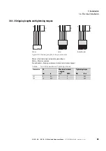
Page 69: ...L2 N PE for the mains side supply voltage U V PE for the connection to the motor BR DC PE for an external brake resistor Figure 38 Connection in power section schematic The number and the arrangement...

Page 70: ...single phase supply voltage DC1 S1 115 V DC1 S2 230 V Hint Connection to terminal L3 not permissible DC Negative DC link connection if using an external DC power supply or DC link coupling The termin...

Page 71: ...degree of protection On units with an IP66 degree of protection the connection area is located behind the lower enclosure cover To open the cover release the two latches by turning them counterclockw...

Page 72: ...le phase AC motor DC1 S1 115 V DC1 S2 230 V FS2 Connection with single phase supply voltage DC1 S1 115 V DC1 S2 230 V Hint Connection to terminal L3 not permissible Motor connection for single phase A...

Page 73: ...ping lengths in the power section Mains Electrical power network supply voltage Motor Motor connection Brake Resistor Braking resistance connection to brake chopper Table 8 Terminal capacities and tig...

Page 74: ...ecoming unbraided i e by pushing the separated plastic covering over the end of the shielding or with a rubber grommet on the end of the shielding Terminate the cable screen across a large area at the...

Page 75: ...e Textile and PVC fillers If additional subassemblies such as contactors overload relays or terminals are found in a motor feeder the motor cable s screening can be interrupted close to these assembl...

Page 76: ...the upper enclosure cover will feature three additional knockouts for routing control and bus cables If necessary the corresponding plastic covers can be removed Control Figure 44 Punching out the kn...

Page 77: ...to the PE terminal Figure 46 Grounding the EMC cable gland Figure 47 Example diagram of EMC gland assembly Make sure that the cable glands have at least an IP66 degree of protection Context Frame size...

Page 78: ...nals and the circuit board to prevent damage through electrostatic discharge NOTICE Do not connect an external voltage source to control signal terminal 1 24 V DANGER Before touching or handling the w...

Page 79: ...e digital inputs 100 mA max Reference potential 0 V terminals 7 and 9 2 DI1 Digital Input 1 8 30 V HIGH Ri 6 k FWD 3 DI2 Digital input 2 8 30 V HIGH Ri 6 k Select Quick dec 4 AI2 DI3 Analog input 2 or...

Page 80: ...arameters can be changed with Parameter DXC EXT expansion modules with IP20 degree of protection only section 4 7 2 DXC EXT 2RO output expansion page 100 and section 4 7 3 DXC EXT 2RO1AO output expans...

Page 81: ...cards will be inserted in place above the keypad In the case of devices with an IP66 degree of protection they will be found on the inside of the terminal cover 3 6 2 4 Connection examples Figure 50...

Page 82: ...d plate you can twist the screen braid at the end and connect to the protective earth with a cable lug To prevent EMC disturbance this twisted shielding connection should be made as short as possible...

Page 83: ...d to each other via the common reference potential 0 V control signal terminals 7 and 9 External control voltage through PLC Digital inputs DI1 and DI3 are driven by digital PLC outputs 24 V external...

Page 84: ...uency Drives 05 21 MN040058EN www eaton com Figure 53 Connecting example for relay output Note Depending on the type of load we recommend the use of a suppressor circuit when using the relay output 25...

Page 85: ...onfiguration of the RJ45 interface Pin Meaning 1 CANopen 2 CANopen 3 0 V 4 OP Bus 5 OP Bus 6 24V 7 Modbus RTU A RS485 8 Modbus RTU B RS485 The way the RJ45 interface works is described in the followin...

Page 86: ...ows Table 14 Configuration of the control signal terminals When the device is set to its default settings the setpoint value for operation can be set using the potentiometer The REV 0 FWD selector swi...

Page 87: ...his case parameter P 15 must be used to select the EXTFLT external fault setting for DI3 and parameter P 47 must be set to a value of 6 Ptc th Figure 56 Thermistor connection The thermistors and therm...

Page 88: ...S 20 DC1 S OE1 Variable Frequency Drives 05 21 MN040058EN www eaton com 3 7 Block diagrams The following block diagrams show all the connection terminals on a DC1 S variable frequency drive and their...

Page 89: ...tion DC BR DC V U M 1 L1 L EMC L2 N DC1 S1 1 AC 110 115 V DC1 S2 1 AC 200 240 V 50 60 Hz PES 2 DI1 Start 24 V 3 DI2 4 DI3 AI2 f Fix1 5 10 V Out 10 mA 10 V 6 AI1 DI4 REF 7 0 V 1 24 V Out 100 mA 8 AO DO...

Page 90: ...Figure 58 Block diagram DC1 S1 A66 DC1 S2 A66 2 DI1 3 DI2 4 DI3 AI2 5 10 V Out 10 mA 6 AI1 DI4 7 0 V 1 24 V Out 100 mA 8 0 10 V 20 mA AO 24 V DO 9 0 V 10 11 6 A 250 VAC 5 A 30 VDC CPU PIN 8 PIN 2 PIN...

Page 91: ...e phase mains supply voltage and single phase motor connection 2 DI1 24 V 3 DI2 NOT USED FWD 4 DI3 AI2 5 10 V Out 10 mA 10 V 6 AI1 DI4 f Soll 7 0 V 1 24 V Out 100 mA REV OFF FWD 8 0 10 V 20 mA AO 24 V...

Page 92: ...3 Installation 3 7 Block diagrams 88 DC1 S 20 DC1 S OE1 Variable Frequency Drives 05 21 MN040058EN www eaton com...

Page 93: ...Device Type Frame size Maximum terminal capacity Input current ILN Cross sectional area gauge that should be used for the power supply L1 L L2 N L3 PE Output current rated operational current Ie Cros...

Page 94: ...pole N FAZ B 2 2 pole Rated operating voltage 230 115 V AC Switching capacity 15 kA Fuse Rated operating voltage up to 500 V AC Switching capacity 50 kA Size DII E27 DIII E33 Fuse base S27 S33 Fuse Cl...

Page 95: ...pole in P1DILEM paralleling links can be broken off 4 pole Ith 60 A open 3 pole Ith 50 A open The AC 1 current carrying capacity of the DILEM open contactor increases by a factor of 2 5 when using a P...

Page 96: ...ns voltage 115 V Mains voltage 50 60 Hz ULN 110 10 115 10 V Ue 115 V AC single phase U2 115 V AC single phase DC1 S17D0 8 5 DX LN1 009 17 1 DX LN1 009 13 DC1 S1011 12 5 DX LN1 018 22 8 DX LN1 013 24 N...

Page 97: ...frame size DX EMC L Low leakage current For more information and technical data on DX EMC radio interference suppression filters please refer to instruction leaflet IL04012017Z The maximum motor cabl...

Page 98: ...ermittent braking with a cycle time tC of 120 seconds and a pulse power PPeak equal to the maximum braking power Pmax of the variable frequency drive with the rated motor output Figure 64 DC1 S variab...

Page 99: ...refabricated cables The braking chopper is activated with parameter P 34 section 6 6 3 Extended parameter group page 148 For more information and technical data on the DX BR braking resistors listed h...

Page 100: ...directly to the plug in control signal terminals on DC1 S variable frequency drives making it easy to expand the drives functionality Figure 65 Connecting DXC accessories to the control signal termina...

Page 101: ...on terminals For more information on the coupling modules and on output expansions please refer to Application Note AP040032 DC1 I O Configuration Connection terminal Signal Description Default Settin...

Page 102: ...digital input DI4 13 DI4 Digital Input 41 DXC EXT IO110 100 V 10 120 V 10 DXC EXT IO230 200 V 10 240 V 10 1 Analog input AI1 terminal 6 and digital input DI4 terminals 12 and 13 cannot be used at the...

Page 103: ...cted to the expansion module meaning it can only conduct a relatively low current 1A DANGER Dangerous voltage Expansion modules DXC EXT IO110 and DXC EXT IO230 must not be placed into operation until...

Page 104: ...rol voltage for the digital inputs 100 mA max Reference potential 0 V terminal 7 2 DI1 Digital Input 1 8 30 V HIGH Ri 6 k FWD 3 DI2 Digital input 2 8 30 V HIGH Ri 6 k Select Quick Dec 4 AI2 DI3 Analog...

Page 105: ...der for the output to function as a digital output If the parameter is set to a value greater than 7 relay output K2 will not work properly For detailed instructions on how to install the module pleas...

Page 106: ...DI3 Analog input 2 or digital input 3 analog 0 10 V Ri 72 k 0 4 20 mA RB 500 digital 8 30 V HIGH Ri 72 k Select AI1REF f Fix1 5 10 V Reference voltage 10 mA max Reference potential 0 V terminals 7 an...

Page 107: ...rent 1A DANGER Dangerous voltage Expansion module DXC EXT 2RO1AO must not be placed into operation until all mounting and installation work has been completed plugged in and connected to the DC1 S var...

Page 108: ...ncy drive ready for operation Typical operating mode DXC EXT 2RO1AO control signal terminals 12 13 closed There is an enable signal for operation FWD READY and RUN messages Green indicator light for e...

Page 109: ...three microswitches can be used to directly drive from left to right the three digital inputs DI1 DI2 and DI3 with the internal control voltage 24 V DC Meanwhile the POTI PCB mount potentiometer can...

Page 110: ...betweenvariablefrequencydriveand PC MN040003 DX SPL R145 2SL1PL RJ45 8 pin splitter 2 sockets 1 plug on short connection cable lL04012023Z DX SPL RJ45 3SL RJ45 8 pin splitter 3 sockets lL04012023Z DX...

Page 111: ...s 1 L and L2 N of the variable frequency drive Measure the mains cable s insulation resistance between the individual phase conductors and between each phase conductor and the protective conductor The...

Page 112: ...ns in this documentation have been observed The applicable standards in the IEC HD 60364 DIN VDE 0100 VDE 0100 series have been observed The continuity of all associated protective conductors and equi...

Page 113: ...equency drive has been earthed properly PE 6 All electrical connections in the power section L1 L L2 N U V DC DC BR PE have been connected properly while taking into account the degree of protection a...

Page 114: ...nals The control signal terminals are isolated from the line power potential There can be a dangerous voltage on the relay terminals 10 11 even if the variable frequency drive is not being supplied wi...

Page 115: ...motor side must not be opened while the motor is in operation Inching operation of the motor with contactors and switching devices in the output of the variable frequency drive is not permissible NOT...

Page 116: ...the mains connection terminals L1 L L2 N the switched mode power supply unit SMPS in the internal DC link will be used to generate the control voltage and light up the 7 segment LED display StoP At t...

Page 117: ...sted based on the V Hz curve just like on three phase motors Voltage at desired speed Voltage The voltage is increased linearly from V Boost P 11 all the way to the rated motor operating voltage P 07...

Page 118: ...oost P 33 parameter to the maximum possible value 150 0 s This will allow the voltage to increase slowly and make it possible to easily adjust the start voltage and the startup behavior Start the driv...

Page 119: ...r the motor starts with a rising voltage After the motor starts the current will increase As soon as the motor reaches its full speed the current will decrease rapidly If the time set with t Boost is...

Page 120: ...rate the control voltage and the 7 segment LED display will light up StoP At this point the variable frequency drive will be ready for operation correct operating status and in Stop mode The start ena...

Page 121: ...quency Drives 05 21 MN040058EN www eaton com 117 Example Table 26 Selector switch for DC1 A6S Switch position Parameter Description P 12 P 15 Default Setting REV quick stop STOP FWD Start 0 5 Speed co...

Page 122: ...ual parameters Display 7 digital LEDs Push buttons If you intend to use an external keypad and or a parameter copying stick with the DC1 CE1 variable frequency drive please note that only models DX KE...

Page 123: ...l is being used integrated DX KEY LED or external DX KEY OLED Button Attribute ID Explanation OK Navigating in parameter mode Opens and closes the parameter interface press the button and hold it down...

Page 124: ...5 Operation 5 7 Handling the keypad 120 DC1 S 20 DC1 S OE1 Variable Frequency Drives 05 21 MN040058EN www eaton com...

Page 125: ...right Display values P00 01 P00 20 DC1 S ro P00 21 P00 50 DC1 S E1 ro Basis parameters P 01 P 14 DC1 S rw Expansion P 15 P 55 DC1 S rw Expansion version 1 P 60 P 68 DC1 S E1 rw Commands Description P...

Page 126: ...the OK button and hold it down for two seconds in order to access the parameter interface The display will show the parameter that was last used Use the and buttons to select parameter P 14 Press the...

Page 127: ...to select the configuration for the control signal terminals More specifically you can select predefined terminal configurations by setting P 15 to a value between 0 and 13 The setting digital analog...

Page 128: ...Pulse STOP signal must always be present when operating the drive If the signal is not present it will not be possible to start the drive the drive will ramp down to zero To start all that is required...

Page 129: ...or with the UP and DOWN commands and fixed frequency 4 f Fix4 which is set with P 23 Low digital setpoint value High f Fix4 Select f Fix Bit0 f Fix Bit1 Used to select a fixed frequency with digital c...

Page 130: ...I1 REF Used to select between setpoint values Low setpoint from the PI controller s output High AI1 Select PI REF f Fix1 Used to select between setpoint values Low setpoint from the PI controller s ou...

Page 131: ...AI1 REF 4 START Select AI1 REF AI2 REF AI2 REF AI1 REF 5 START Select Quick dec Select AI1 REF f Fix1 AI1 REF 6 START No function EXTFLT AI1 REF 7 START Select Quick dec EXTFLT AI1 REF 8 START No fun...

Page 132: ...l 6 0 START UP DOWN No function 1 Not permissible 2 START UP DOWN Select DIG REF f Fix1 3 START UP EXTFLT DOWN 4 START UP Select DIG REF AI1 REF AI1 REF 5 Not permissible 6 START No function EXTFLT Se...

Page 133: ...on No function 1 Not permissible 2 Not permissible 3 START Select BUS REF f Fix1 EXTFLT No function 4 Not permissible 5 Not permissible 6 START Select BUS REF AI1 REF EXTFLT AI1 REF 7 START Select BUS...

Page 134: ...2 Not permissible 3 START Select BUS REF f Fix1 EXTFLT No function 4 Not permissible 5 Not permissible 6 START Select BUS REF AI1 REF EXTFLT AI1 REF 7 START Select BUS REF DIG REF EXTFLT No function 8...

Page 135: ...REF 2 Not permissible 3 START Select PI REF f Fix1 EXTFLT PI feedback 4 Not permissible 5 Not permissible 6 Not permissible 7 Not permissible 8 Not permissible 9 Not permissible 10 Not permissible 11...

Page 136: ...F PI feedback AI1 REF 2 Not permissible 3 START Select PI REF f Fix1 EXTFLT PI feedback 4 Not permissible 5 Not permissible 6 Not permissible 7 Not permissible 8 Not permissible 9 Not permissible 10 N...

Page 137: ...No function 1 Not permissible 2 Not permissible 3 START Select BUS REF f Fix1 EXTFLT No function 4 Not permissible 5 Not permissible 6 START Select BUS REF AI1 REF EXTFLT AI1 REF 7 START Select BUS RE...

Page 138: ...issible 3 START Select BUS REF f Fix1 EXTFLT No function 4 Not permissible 5 Not permissible 6 START Select BUS REF AI1 REF EXTFLT AI1 REF 7 START Select BUS REF DIG REF EXTFLT No function 8 Not permi...

Page 139: ...rmissible 5 Not permissible 6 Not permissible 7 Not permissible 8 Not permissible 9 Not permissible 10 Not permissible 11 Not permissible 12 Not permissible 13 ENA No function EXTFLT No function 14 No...

Page 140: ...TART Select AI2 REF AI1 REF AI2 REF AI1 REF 5 Not permissible 6 FWD No function EXTFLT AI1 REF 7 Not permissible 8 START No function Select f Fix Bit0 Select f Fix Bit1 9 Not permissible 10 Not permis...

Page 141: ...ible 5 Not permissible 6 Not permissible 7 Not permissible 8 Not permissible 9 Not permissible 10 Not permissible 11 Not permissible 12 Not permissible 13 ENA No function EXTFLT No function 14 Not per...

Page 142: ...e 4 Not permissible 5 Not permissible 6 Not permissible 7 Not permissible 8 Not permissible 9 Not permissible 10 Not permissible 11 Not permissible 12 Not permissible 13 ENA No function EXTFLT No func...

Page 143: ...P 03 P 04 cannot be increased a larger device may be required I t trP Motor overload The thermal protection mechanism has tripped as a result of the device being run above the rated motor current set...

Page 144: ...e is too hot Check to make sure that the variable frequency drive is being operated within the ambient temperature range specified for it IP20 devices max 50 C IP66 devices max 40 C Make sure that coo...

Page 145: ...read the parameters from the variable frequency drive PASS t Parameter transfer to variable frequency drive successful FAiL P The parameter set stored in the DX COM STICK2 is for a different rating di...

Page 146: ...2 Level of the signal applied to analog input 2 after scaling and offsets have been applied P00 03 Frequency Reference P 01 P 01 Frequency Reference in Hz Will be calculated into rpm when motor data...

Page 147: ...tor current log Shows the last eight motor current values before the device was switched off due to a fault The sample interval is 256 ms P00 18 DC Link V Ripple0 Log 0 V 1000 V DC bus Voltage Ripple...

Page 148: ...rred P00 36 FaultCounter Overtemperature Heatsink 0 65535 Counts how often Overtemperature Heatsink occurred P00 37 FaultCounter Overcurrent Brake Chopper 0 65535 Counts how often Overcurrent Brake Ch...

Page 149: ...Nom Speed P 10 0 the minimum speed limit will be displayed in rpm 0 0 Hz P 03 t acc 0 00 s 600 s Sets the acceleration ramp time in seconds The time interval set in P 03 represents the time taken to...

Page 150: ...will indicate that there is an overload If this situation persists for a prolonged period of time the device may trip due to overloading Display I t trP Ie P 09 Motor Nom Frequency 25 hz 500 Hz The r...

Page 151: ...ble Pressing the keypad START button toggles between forward and reverse 3 Modbus Control Control via Modbus RTU communication 4 Modbus Control Ramp times via Modbus 5 PI controller with external actu...

Page 152: ...case of wire break 6 r 20 4 mA Ramps to f fix1 P 20 in case of wire break 7 10 0 V 0 P 17 Switching Frequency 0 5 Power stage switching frequency Higher frequency reduces the audible ringing noise fr...

Page 153: ...ax Selection via a digital control signal If P 09 is changed the value is reset to default 0 0 Hz P 24 t QuickDec 0 00 s 600 0 s Quick Stop Ramp In default the second deceleration ramp is activated by...

Page 154: ...e up to 5 attempts to restart at 25 second intervals The drive must be powered down to reset the counter The number of restart attempts are counted and if the drive fails to start on the final attempt...

Page 155: ...edforbraking resistors with a 200 W rating 0 Disabled 1 Enabled with software protection 2 Enabled without software protection 3 Enabled during speed reference change with software protection 4 Enable...

Page 156: ...defines the password needed to get access to the advanced parameter set P 37 100 Access via P 14 101 P 38 Parameter Lock 0 1 Determines whether to lock the parameters 0 OFF All parameters can be chan...

Page 157: ...t with P 45 1 analog input 1 0 P 45 PID1 Set Point Digital 0 00 100 00 Digital set point controller 1 Digital set point of the PI controller in case P 44 0 0 00 P 46 PID 1 Feedback 1 Source 0 5 Define...

Page 158: ...nged by any source 1 All parameters locked can only be changed by the SWD Device 0 P 53 Action Communication Loss 0 4 Device reaction after occuring of Communication Loss Possibilities device dependen...

Page 159: ...t error message you can either switch off the supply voltage or press the STOP pushbutton Error messages a maximum of four are stored in parameter P00 13 Error messages can also be reset with a new st...

Page 160: ...6 Parameter structure 6 7 Fault messages 156 DC1 S 20 DC1 S OE1 Variable Frequency Drives 05 21 MN040058EN www eaton com...

Page 161: ...nt Operation within a temperature range of 40 to 50 C does not conform to UL listing Storage C 40 60 frost free and condensation free Degree of pollution Non conductive dust permissible Transport Clas...

Page 162: ...eduction every 100 m maximum 2000 with UL approval maximum 4000 without UL approval Degree of protection IP20 NEMA 0 IP66 NEMA 4X Protection against contact BGV A3 VBG4 finger and back of hand proof M...

Page 163: ...able f2 Hz 0 50 60 max 500 Hz resolution Hz 0 1 Rated operation current Ie A 4 3 11 Overload current for 60 s every 600 s il 150 Overload current for 3 75 s every 600 s il 175 Switching frequency doub...

Page 164: ...resolution 12 bits accuracy 1 to the final value Response time tr ms 16 Input voltage range US V 0 10 DC Ri 72 k Input current range IS mA 0 4 20 RB 500 Relay output RO1 Quantity 1 relay Relay contact...

Page 165: ...ed operational current 7D0 7 0 A DC1 S1 series S For connecting single phase motors 1 115 V Mains connection DC1 S2 011 FB Power section characteristics NN without radio interference suppression filte...

Page 166: ...side Number of phases single phase single phase Rated operating voltage ULN V 110 10 115 10 48 62 Hz 99 126 0 Input current phase current ILN A 8 5 12 5 Switching frequency pulse frequency Default Set...

Page 167: ...rimary side Number of phases single phase single phase single phase Rated operating voltage ULN V 200 10 240 10 50 60 Hz 180 264 0 48 62 Hz 0 Input current phase current ILN A 6 9 3 14 Minimum braking...

Page 168: ...0 Dimensions and weights DC1 S in IP20 c c1 VAR EMC b b1 a a1 1 2 3 4 5 6 7 8 9 10 11 1 2 b2 FS Type a a1 b b1 b2 c c1 1 2 m mm in mm in mm in mm in mm in mm in mm in mm in mm in kg lbs FS1 DC1 S17D0...

Page 169: ...and weights DC1 S in IP66 REV FWD 0 ON OFF PWR b a c a1 c1 b1 b2 a1 b1 1 2 a1 b1 FS Type a a1 b b1 b2 c c1 1 2 m mm in mm in mm in mm in mm in mm in mm in mm in mm in kg lbs FS1 DC1 S17D0 DC1 S24D3 DC...

Page 170: ...7 Technical Data 7 3 Dimensions 166 DC1 S 20 DC1 S OE1 Variable Frequency Drives 05 21 MN040058EN www eaton com...

Page 171: ...l section 74 Control signal terminals 82 Cooling 49 Cooling air 50 Coupling interfacing components 97 D Data technical 157 DC Link Voltage 25 36 Default Setting 7 Degree of protection 13 17 18 Deratin...

Page 172: ...st of revisions 5 M Magnet system 27 Mains chokes 92 Mains connection 29 Mains contactors 33 91 Mains supply voltages 8 Mains voltage 20 30 Maintenance 24 Manufacturing date 13 Miniature circuit break...

Page 173: ...60364 I IEC 60364 4 41 I IEC EN 60204 1 I Steinmetz circuit 40 44 Storage 24 Strip length 69 Switch disconnectors 38 Switching Frequency 93 System overview 10 T t Boost P 33 115 Terminal capacity 69...

Reviews: