3 Installation
3.5 EMC installation
DC1-S…20…, DC1-S…OE1 Variable Frequency Drives
05/21 MN040058EN
www.eaton.com
57
3.5.2 Grounding
The protective earth (PE) in the control panel should be connected from the
mains supply to a central earth point (mounting plate, system earth).
The PE conductor’s cross-sectional area must be at least as large as that of
the incoming mains supply cable. If there are leakage currents greater than
3.5 mA, the PE conductor must have a minimum cross-sectional area of
10 mm
2
.
Every variable frequency drive must be individually connected to the power
supply system’s protective earth directly at the location of installation
(system earthing). This protective earth must not pass through any other
devices.
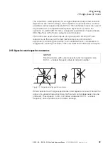
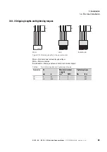
All protective conductors must be routed in a star-shaped layout extending
from the central earth point, and all of the drive system’s conductive
components must be connected.
Figure 33: Star-shaped layout extending from earth point
The earth-fault loop impedance must comply with all locally applicable
industrial safety regulations. In order to meet UL standards, UL-listed ring
cable lugs must be used for all earth wiring connections.
3.5.2.1 Protective earth
This refers to the legally required protective earth for a variable frequency
drive. An earthing terminal on the variable frequency drive, or the system
earth, must be connected to a neighboring steel element in the building
(beam, ceiling joist), an earth electrode in the ground, or a mains earth bus.
The earth points must meet the requirements set forth by the applicable
national and local industrial safety regulations and/or regulations for electrical
systems.
→
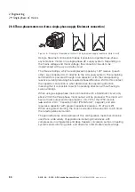
Avoid ground loops when installing multiple variable frequency
drives in one control panel. Make sure that all metallic devices
that are to be grounded have a broad area connection with the
mounting plate.
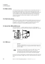
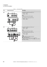
MOTOR
Brake
Resistor
MAINS
DC1-S1…
DC1-S2…
Summary of Contents for PowerXL
Page 4: ......

