background image

Page 5

9130 UPS-EN

ENGLISH

2. Installation

This section explains:

Equipment inspection


l

Unpacking the cabinet


l

Checking the Accessory Kit


l

Product installation


l

Connecting the internal battery


l

Connecting the EBM(s)


l

Installation requirements


l

2.1 

Inspecting the Equipment 

If any equipment has been damaged during shipment, keep the shipping cartons and packing materials 
for the carrier or place of purchase and file a claim for shipping damage. If you discover damage after 
acceptance, file a claim for concealed damage.
To file a claim for shipping damage or concealed damage:  
1) File with the carrier within 15 days of receipt of the equipment; 
2) Send a copy of the damage claim within 15 days to your service representative.

Check the battery recharge date on the shipping carton label. If the date has passed and the 
batteries were never recharged, do not use the UPS. Contact your service representative.

2.2 

Unpacking the Cabinet

Unpacking  the  cabinet  in  a  low-temperature  environment  may  cause  condensation  to  occur 


l

in and on the cabinet. Do not install the cabinet until the inside and outside of the cabinet are 
absolutely dry (hazard of electric shock).

The cabinet is heavy (see page 31). Use caution to unpack and move the cabinet.


l

Unpack the equipment and remove all the packing materials and shipping cartoon (

see figure 2

 for 

unpacking 5000 & 6000 VA UPS and External battery cabinets).

Note!

 Do not lift the UPS or External Battery Cabinets from the front panel.

Figure 2. Unpacking 5000/6000 VA UPS and external battery cabinet.

Discard or recycle the packaging in a responsible manner, or store it for future use.
Place the cabinet in a protected area that has adequate airflow and is free of humidity, flammable gas, 
and corrosion.

Summary of Contents for Powerware 9130

Page 1: ...ENGLISH EATON 9130 UPS 5000 6000 VA User s guide Copyright 2010 EATON All rights reserved Service and support Call your local service representative 9130 UPS EN ...

Page 2: ...R TO OPERATOR S MANUAL Refer to your operator s manual for additional information such as important operating and maintenance instructions Do not discard the UPS or the UPS batteries in the trash This product contains sealed lead acid batteries and must be disposed as it s explain in this manual For more information contact your local recycling reuse or hazardous waste center This symbol indicates...

Page 3: ... Panel Functions 14 4 2 Operating Modes 17 4 3 UPS Startup and Shutdown 18 4 4 Transferring the UPS Between Modes 19 4 5 Retrieving the Event Log 19 4 6 Setting Power Strategy 19 4 7 Configuring Bypass Settings 19 4 8 Configuring Battery Settings 20 5 Communication 5 1 Installing Communication Options and Control Terminals 21 5 2 Communication Options 21 5 3 Eaton Power Management Software Suite 2...

Page 4: ...anding performance and reliability the Eaton 9130 s unique benefits include True online double conversion technology with high power density utility frequency l independence and generator compatibility ABM technology that uses advanced battery management to increase battery service life l optimize recharge time and provide a warning before the end of useful battery life Selectable High Efficiency ...

Page 5: ...he shipping carton label If the date has passed and the batteries were never recharged do not use the UPS Contact your service representative 2 2 Unpacking the Cabinet Unpacking the cabinet in a low temperature environment may cause condensation to occur l in and on the cabinet Do not install the cabinet until the inside and outside of the cabinet are absolutely dry hazard of electric shock The ca...

Page 6: ...ngineerUPS eaton com 9130 UPS EN Figure 3 UPS Accessory kit If you ordered an optional Extended Battery Module EBM verify that the following additional item is included with the EBM EBM user s guide l Power cable l Figure 4 EBM Accessory kit Discard the EBM user s guide if you are installing the EBM with a new UPS at the same time Use the UPS user s guide to install both the UPS and the EBM 2 4 Pr...

Page 7: ...2 Connect the internal battery connector see figure 6 Connect the black connectors together Press the two parts tightly together to ensure a proper connection Figure 6 Connecting the UPS internal batteries 3 Replace the UPS front cover To replace the cover verify that the ribbon cable is protected then insert the clips on the back of the cover into the cabinet and push firmly to snap the cover int...

Page 8: ... adequate bend radius and strain relief exist for each cable 3 When using external battery cabinets the number of EBMs should be set throw the LCD panel in the Battery settings section see Configuring battery settings on page 20 4 Continue to Installation requirements on page 8 Figure 7 Connecting the EBMs 2 7 Installation requirements Required protective devices and cable cross sections 1 Recomme...

Page 9: ...required Figure 10 UPS with separate Normal and Bypass inputs Figure 11 Change in SEA between upstream and downstream or galvanic isolation required Figure 12 The transformer is not necessary if Normal and Bypass inputs are connected to the same source l and wires cross sections and wires lengths on Input and Bypass inputs are identical l and upstream protection is provided by only one switch with...

Page 10: ...galvanic isolation required Figure 14 8 10 11 Frequency converter without Bypass input Figure 15 Configuration used when the frequency of the application differs from the Mains example marine requirements Bypass Bypass Bypass Input Input Input Input Load Load Load Load Main low voltage switchboard MLVS MLVS1 MLVS1 MLVS1 MLVS2 MLVS2 MLVS2 Output Output Output Output ...

Page 11: ... 2 Common input sources connection This type of connection must be carried out by qualified electrical personnel Before carrying out any connection check that the upstream protection device Input source is open O OFF Always connect the earthing wire first JP L N L N L N BYPASS INPUT OUTPUT 1 Make sure the metal jumper is connected see figure 17 2 Insert the Input source cable through the cable gla...

Page 12: ...d 7 Connect the 3 cables to the output terminal block 8 Put back and secure the terminal block cover with the 2 screws 9 Tightened the cable glands Figure 18 3 4 Frequency converter connection This type of connection must be carried out by qualified electrical personnel Before carrying out any connection check that the upstream protection device Input source is open O OFF Always connect the earthi...

Page 13: ...e installed see Configuring the UPS for EBMs on page 20 to set the number of installed EBMs 10 To change any other factory set defaults see Operation on page 14 If you are powering RCD type loads with high inrush current it is possible to first start on bypass 1 In standby mode enable the user setting Start on Bypass disabled by default 2 Press the on button to start the UPS The UPS will start on ...

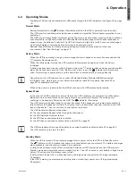
Page 14: ...ency operation Green Flashing A new information message is active On The UPS is in Battery mode Yellow Flashing The battery voltage is below the warning level On The UPS is in Bypass mode Yellow On The UPS has an active alarm or fault See Troubleshooting on page 33 for additional information Red Changing the Language Press and hold the first button on the left for approximately three seconds to se...

Page 15: ... Password Enabled Disabled If Enabled is selected the password is USER Disabled Audible Alarms Enabled Disabled Enabled Set Date and Time NOTE time is a 24 hour clock Set Year Month Day Hours Minutes Date yyyy mm dd Time hh mm 2008 01 01 12 00 Signal Inputs Setup Not Used Force Bypass Remote Shutdown Delayed Shutdown On Generator Building Alarm 1 Active High Low See Programmable Signal Inputs on p...

Page 16: ...15 of nominal Bypass Voltage High Limit 4 5 20 of nominal 10 of nominal Qualify Bypass Never When in Spec Always on UPS Fault Always When in Spec Synchronization Window Sync Disabled 0 5 Hz 1 0 Hz 2 0 Hz 3 0 Hz 3 Hz Unsynchronized Transfers Enabled Disabled Enabled Number of Battery Strings 0 1 2 10 See Configuring the UPS for EBMs on page 18 1 Battery Charge Mode ABM Cycling Constant ABM Cycling ...

Page 17: ... page 33 for estimated runtimes When utility power is restored after the UPS shuts down the UPS automatically restarts Bypass Mode In the event of a UPS overload or internal failure the UPS transfers your equipment to utility power Battery mode is not available and your equipment is not protected however the utility power continues to be passively filtered by the UPS The indicator illuminates The ...

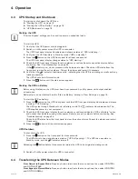
Page 18: ...must have been powered by utility power with output enabled at least once Battery start can be disabled See the Start on Battery setting in User Settings on page 16 To start the UPS on battery 1 Press the button on the UPS front panel until the UPS front panel display illuminates and shows a status of UPS starting The UPS cycles through Standby mode to Battery mode The indicator illuminates solid ...

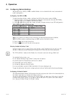
Page 19: ...shown in table 20 on page 32 Bypass Voltage Low Limit The default disables a transfer to Bypass if the measured bypass voltage level is below the nominal output voltage minus 15 You can configure the setting for another percentage of nominal This setting can be overruled by the Qualify Bypass setting Bypass Voltage High Limit The default disables a transfer to Bypass if the measured bypass voltage...

Page 20: ...en appears Running Automatic Battery Tests Automatic battery tests run approximately every 30 days unless disabled During the test the UPS transfers to Battery mode and discharges the batteries for 25 seconds under the existing load The UPS on Battery notice and the Battery Low alarm do not activate during a battery test For automatic battery tests to run the Automatic Battery Support Tests settin...

Page 21: ...cation Options for detailed information 2 Route and tie the cable s out of the way 3 Continue to Operation on page 14 to start up the UPS 5 2 Communication Options The Eaton 9130 has serial communication capabilities through the USB and RS 232 communication ports or through a connectivity card in the available communication bay The UPS supports two serial communication devices according to the fol...

Page 22: ...es a Low V signal for 5 seconds the UPS executes the command selected by the Signal Inputs setting in User Settings on page 15 3 When the selected condition is active output signals on Pins 1 and 8 shift from Low positive voltage to High negative voltage When the condition no longer exists the output signal returns to Low Connectivity Cards Connectivity cards allow the UPS to communicate in a vari...

Page 23: ...ontact open shut down of UPS To return to normal operation deactivate the external remote shut down contact and restart the UPS from the front panel Figure 24 4 Plug the RPO connector into the back of the UPS and fix the screws 5 Connect and restart the UPS according to the previously described procedures 6 Activate the external remote shut down contact to test the function You can set the RPO pol...

Page 24: ...nd one RPO terminal input See figure 21 on page 21 for the locations of the ports Configure the inputs with the Signal Inputs setting in User Settings on page 15 The table 11 shows the programmable settings for the signal inputs Table 12 shows the operation logic for the signal inputs Table 11 Programmable Signal Inputs Signal Description Not Used The input operates only as a serial input RxD or h...

Page 25: ...on For the UPS manufacturer and model select Eaton and Eaton 9130 If the Eaton brand options are not available in your version of the software select Generic UPSs for the manufacturer and Generic XCP for the model Eaton software suite provides up to date graphics of UPS power and system data and power flow It also gives you a complete record of critical power events and it notifies you of importan...

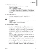
Page 26: ...to keep units running at peak efficiency 6 2 Storing the UPS and Batteries If you store the UPS for a long period recharge the battery every 6 months by connecting the UPS to utility power The internal batteries charge to 90 capacity in less than 3 hours However Eaton recommends that the batteries charge for 48 hours after long term storage If optional EBMs are installed see the recharge times lis...

Page 27: ... grounded remove source l from ground Contact with any part of a grounded battery can result in electrical shock The likelihood of such shock can be reduced if such grounds are removed during installation and maintenance applicable to equipment and remote battery supplies not having a grounded supply circuit ELECTRIC ENERGY HAZARD Do not attempt to alter any battery wiring or connectors l Attempti...

Page 28: ...emove the metal fixing part to free the battery tray see figure 30 Figure 30 Free the battery tray 5 Carefully pull the handle on the battery tray and slide the battery package slowly out onto a flat stable surface use two hands to support the battery package See Recycling the Used Battery or UPS on page 30 for proper disposal Verify that the replacement batteries have the same rating as the batte...

Page 29: ...rack requires a minimum of two people To replace the EBMs 1 Unplug the EBM cable from the UPS If additional EBMs are installed unplug the EBM cable from the battery connector on each EBM 2 Replace the EBM s See Recycling the Used Battery or UPS on page 30 for proper disposal A small amount of arcing may occur when connecting an EBM to the UPS This is normal and will not harm personnel Insert the E...

Page 30: ...al codes for disposal requirements Do not open or mutilate the battery or batteries Released electrolyte is harmful to the skin and l eyes It may be toxic Do not discard the UPS or the UPS batteries in the trash This product contains sealed lead acid batteries and must be disposed of properly For more information contact your local recycling reuse or hazardous waste center Do not discard waste ele...

Page 31: ...cts 1 three pole connector with 1 contact closure Table 14 Extended Battery Module Model List EBM Model Configuration Battery Voltage For Power Ratings PW9130N6000T EBM Tower 240 Vdc 5000 6000 VA Table 15 UPS Model List Model Power Level Rear Panel Diagram PW9130i5000T XL 5000 VA 4500 W Figure 21 on page 21 PW9130i6000T XL 6000 VA 5400 W Figure 21 on page 21 Table 16 Weights and Dimensions Model T...

Page 32: ...l Outputs 200 208 220 230 240V voltage configurable or auto sensing 5000 6000 VA 4 5 5 4 kW Frequency 50 or 60 Hz autosensing or configurable as a frequency converter Output Overload 100 102 Activates Overload alarm Level 1 102 129 Load transfers to Bypass mode after 2 minutes Level 2 130 149 Load transfers to Bypass mode after 30 seconds Level 3 150 Load transfers to Bypass mode after 100 ms Leve...

Page 33: ... 3 000 meters 9 843 ft above sea level Transit Altitude Up to 10 000 meters 32 808 ft above sea level Audible Noise 55 dBA at 1 meter typical Leakage Current 1 5 mA Table 23 Battery Runtimes in Minutes at 100 Load Model Internal Batteries 1 EBM 2 EBMs 3 EBMs 4 EBMs PW9130i5000T XL 9 min 41 min 1 h 19 min 1 h 57 min 2 h 42 min PW9130i6000T XL 6 min 32 min 1 h 03 min 1 h 37 min 2 h 08 min Note Batte...

Page 34: ...isplays 3 Press the Enter button to display the list of conditions You can also retrieve the entire Event Log in ASCII format See Retrieving the Event Log on page 19 The following table describes typical alarms and conditions Alarm or Condition Possible Cause Action On battery LED is on 1 beep every 5 seconds A utility failure has occurred and the UPS is in Battery mode The UPS is powering the equ...

Page 35: ...tteries need charging or service Apply utility power for 48 hours to charge the batteries If the condition persists contact your service representative Power is not available at the UPS output receptacles The UPS is in Standby mode Supply power to the connected equipment press the On Off button for at least 1 second until the front panel displays UPS starting The UPS does not start The power cord ...

Page 36: ...number l Serial number l Firmware version number l Date of failure or problem l Symptoms of failure or problem l Customer return address and contact information l If repair is required you will be given a Returned Material Authorization RMA Number This number must appear on the outside of the package and on the Bill Of Lading if applicable Use the original packaging or request packaging from the H...

Reviews: