31
9395P 250 kVA / 275 kVA / 300 kVA
User’s and Installation Guide
11.
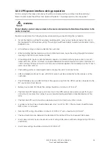
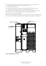
Using hardware from the external wiring terminal hardware kit (see Table 3
‐
9),
connect phase A, B,
and C, and Neutral power wiring from the output
and neutral terminals of each
UPS unit to the
customer-supplied tie cabinet or
load distribution panel. See paragraph 3.2.2 for wiring and
termination requirements.
12.
Proceed to paragraph 4.6.3.
13.
Using hardware from the external wiring terminal hardware kit (see Table 3
‐
9),
connect phase A,
B, and C, and Neutral (if required) power wiring
from output terminals and
neutral terminals to the
critical load. See paragraph 3.2.2 for wiring and termination
requirements.
14.
Proceed to paragraph 4.6.3.
CAUTION
On a UPS that is configured for separate rectifier inputs, all sources that feed the separate
rectifier inputs must be derived from a common ground point.
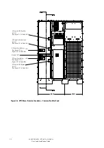
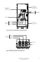
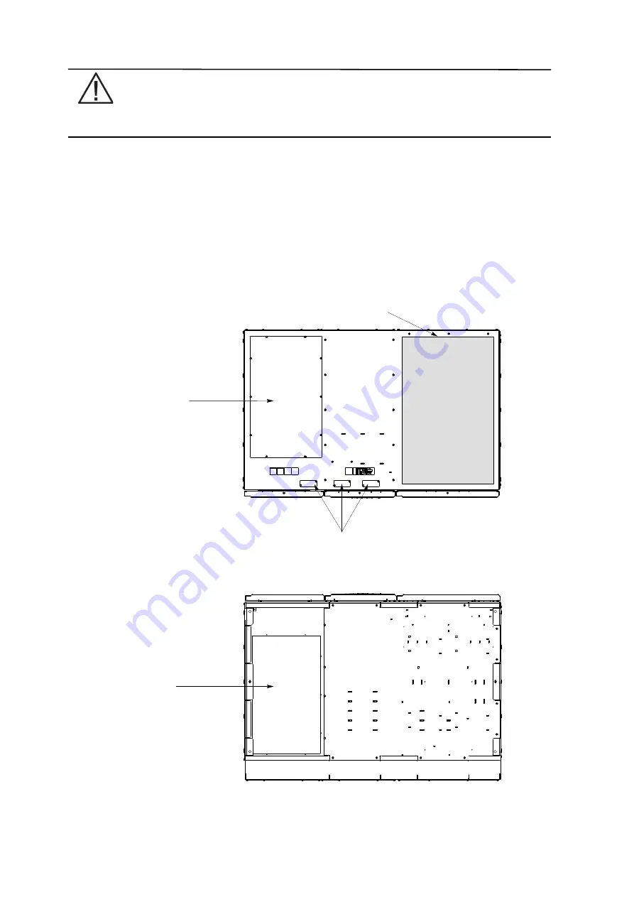
Top Entry Conduit Landing for AC
Input and Output, and DC Input
(Remove panel to drill or punch
conduit holes.)
TOP VIEW
Interface Entry Conduit Landings for TB1 through TB3 Wiring and X-Slot Connections
(Remove panels to drill or punch conduit holes.)
Ventilation Grill Debris Shield (Remove shield before operating system.)
Bottom Entry Conduit Landing for AC
Input and Output, and DC Input
(Remove panel to drill or punch
conduit holes.)
BOTTOM VIEW
Front
Front
Figure 4‐4. Conduit and Wire Entry Locations
Summary of Contents for Power Xpert 9395P 250 kVA
Page 1: ...User s and Installation Guide Power Xpert 9395P UPS 250 kVA 275 kVA 300 kVA...
Page 2: ......
Page 3: ...Power Xpert 9395P UPS 250 kVA 275 kVA 300 kVA User s and Installation Guide...
Page 168: ......
Page 169: ......
Page 170: ...614 01919 00...


