


Eaton Power Xpert 9395C UPS Installation and Operation Manual 164000821—Rev 06
51
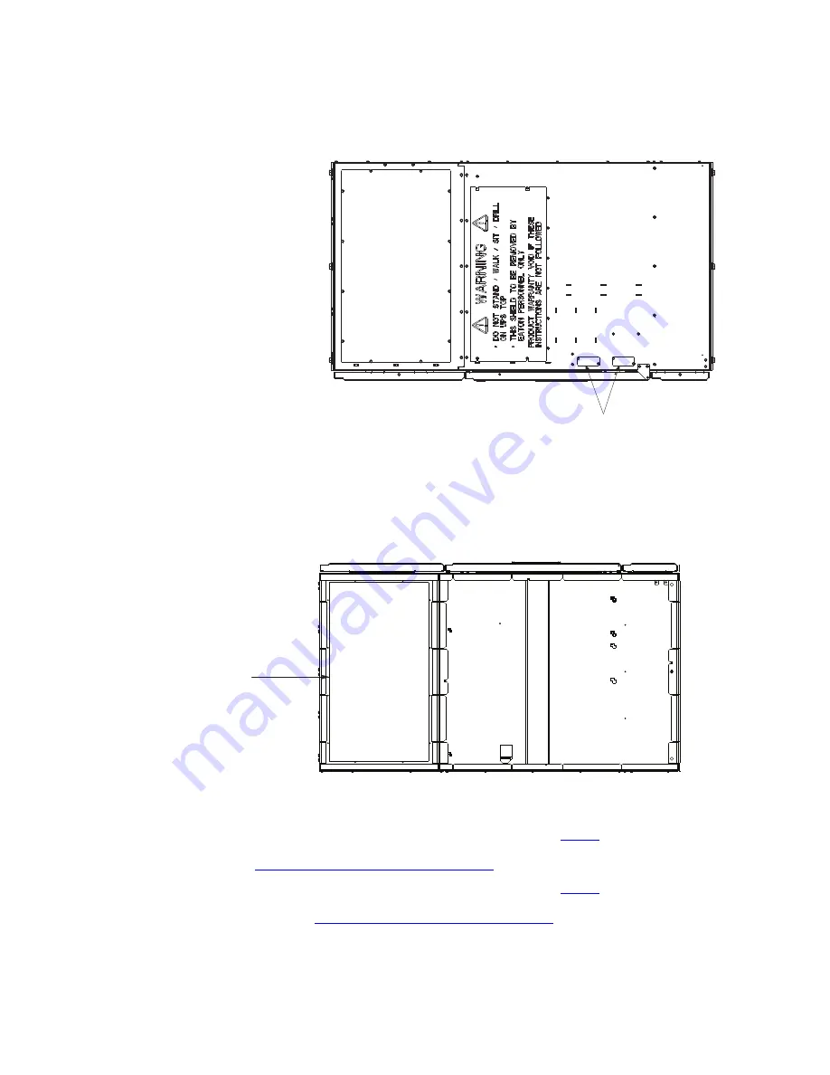
Figure 27. ISBM and PM Section Conduit and Wire Entry Locations
Top Entry Conduit Landing for AC
Input and Output, and DC Input
(Remove panel to drill or punch
conduit holes.)
TOP VIEW
Interface Entry Conduit Landings for TB1
through TB3 Wiring and X-Slot Connections
(Remove panels to drill or punch conduit holes.)
Front
Bottom Entry Conduit Landing for AC
Input and Output, and DC Input
(Remove panel to drill or punch
conduit holes.)
BOTTOM VIEW
Front
CONDUIT LANDING FOR AC INPUT AND OUTPUT AND DC INPUT OPTIONAL TOP OR BOTTOM
4.
Locate the external wiring terminal hardware kit packed on the bottom left side of the ISBM section.
5.
Using hardware from the external wiring terminal hardware kit (see
), connect phase A, B, and C
rectifier input power wiring from the utility source to the rectifier input terminals in the ISBM section. See
paragraph
UPS System Power Wiring Preparation
for wiring and termination requirements.
6.
Using hardware from the external wiring terminal hardware kit (see
), connect phase A, B, and C
wiring from the output terminals of each UPS unit to the customer-supplied tie cabinet or load distribution
panel. See paragraph
UPS System Power Wiring Preparation
for wiring and termination
requirements.
Summary of Contents for Power Xpert 9395C
Page 8: ......
Page 175: ...16400082106 164000821 06...


