background image

112

Eaton Power Xpert 9395 UPS Installation and Operation Manual 164201725—Rev 15

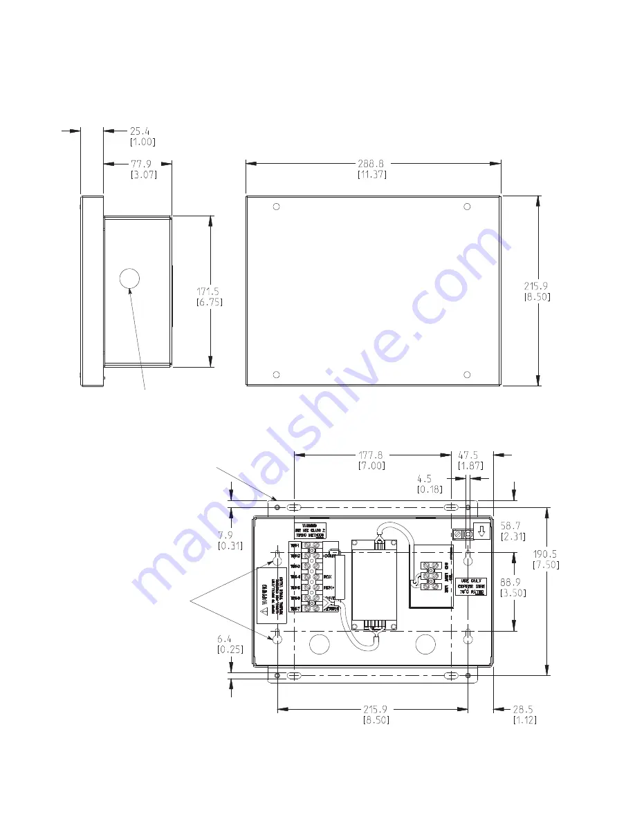
Figure 69. Relay Interface Module II Dimensions

Knockouts Provided

on Five Surfaces

Surface Mount using #10 Pan

Head Screws for Hanging.

(Mount with vent holes facing up.)

Flush Mount using #10 Pan

Head Screws. (Mount with vent holes

facing up.)

Dimensions are in millimeters [inches].

Installing Options and Accessories

Summary of Contents for Power Xpert 9395

Page 1: ... 164201725 Revision 15 450 825 kVA Installation and Operation Manual For use with Two UPM 450 550 kVA Three UPM 650 825 kVA and Plus 1 650 825 kVA UPS Models Power Xpert 9395 UPS Plus 1 UPS and 825 550 UPS ...

Page 2: ... the express written approval of Eaton IMPORTANT SAFETY INSTRUCTIONS SAVE THESE INSTRUCTIONS This manual contains important instructions that you should follow during installation and maintenance of the UPS Please read all instructions before operating the equipment and save this manual for future reference CONSIGNES DE SÉCURITÉ IMPORTANTES CONSERVER CES INSTRUCTIONS Ce manuel comporte des instruc...

Page 3: ...om a host of threats including power outages surges lighting strikes and enable you to monitor and control your power infrastructure We trust that your Eaton 9395 Uninterruptible Power Supply system will deliver high quality reliable backup power for your business and we are committed to your success Please read this Installation and Operation Manual which details the installation and operation pr...

Page 4: ...le license to use the Firmware in conjunction with the operation of the product to which the Firmware pertains or other products as described by Eaton in the Documentation Licensee does not acquire any rights express or implied other than those expressly granted in this Agreement 2 3 Restrictions and Requirements Licensee will not nor will it permit others to modify adapt translate reverse enginee...

Page 5: ...UCT IS AT LICENSEE S SOLE RISK 5 0 GENERAL PROVISIONS 5 1 Update Policy Eaton may from time to time but has no obligation to create Updates of the Firmware or components thereof 5 2 Limitation on Liability NOTWITHSTANDING ANY PROVISION OF THIS AGREEMENT TO THE CONTRARY LICENSEE EXPRESSLY UNDERSTANDS AND AGREES THAT EATON ITS AFFILIATES AND ITS LICENSORS WILL NOT BE LIABLE FOR A ANY DIRECT INDIRECT...

Page 6: ...anctions Programs Pages Programs aspx or to any national of any such country wherever located who intends to transmit or transport the Firmware back to such country ii to any end user who Licensee knows or has reason to know will utilize the Firmware in the design development or production of nuclear chemical or biological weapons or iii to any end user who has been prohibited from participating i...

Page 7: ...onfidential aspects of the Firmware shall not be disclosed to third parties without the prior written consent of Eaton Accordingly Eaton will be entitled to preliminary and permanent injunctive and other equitable relief for any breach of this Section 5 13 5 14 Note on JAVA Support The Firmware may contain support for programs written in JAVA JAVA technology is not fault tolerant and is not design...

Page 8: ......

Page 9: ...aver System and High Alert Modes 6 1 2 11 Harmonic Reduction System HRS 6 1 2 12 Variable Module Management System and High Alert Modes 6 1 2 13 Monitoring and Communication 7 1 3 Battery System 7 1 4 Using This Manual 8 1 5 Conventions Used in This Manual 8 1 6 Symbols Controls and Indicators 8 1 7 For More Information 9 1 8 Getting Help 9 1 9 Warranty 10 2 2 S Sa af fe et ty y W Wa ar rn niin ng...

Page 10: ...9 3 X Slot Connections 88 4 10 Installing a REPO Switch 89 4 11 Installing Options Accessories and Distributed Bypass Control Wiring 92 4 12 Initial Startup 93 4 13 Completing the Installation Checklist 93 5 5 I In ns st ta alllliin ng g O Op pt tiio on ns s a an nd d A Ac cc ce es ss so or riie es s 9 97 7 5 1 Installation Notes 97 5 2 Installing an Optional Powerware Hot Sync CAN Bridge Card 97 ...

Page 11: ... from the UPS Command Menu 167 7 3 4 Start Energy Saver System High Alert Mode from the UPS Command Menu 167 7 3 5 Enable Variable Module Management System Mode from the UPS Command Menu 168 7 3 6 Disable Variable Module Management System Mode from the UPS Command Menu 168 7 3 7 Start Variable Module Management System High Alert Mode from the UPS Command Menu 169 7 3 8 Starting the UPS in Bypass M...

Page 12: ...1 Start Energy Saver System High Alert Mode from the Bypass Command Menu 185 7 4 12 Enable Variable Module Management System Mode from the Bypass Command Menu 186 7 4 13 Disable Variable Module Management System Mode from the Bypass Command Menu 186 7 4 14 Start Variable Module Management System High Alert Mode from the Bypass Command Menu 187 7 4 15 Starting the UPS UPMs 187 7 4 16 Starting a Sin...

Page 13: ...ode 225 8 8 C Co om mm mu un niic ca at tiio on n 2 22 27 7 8 1 X Slot Cards 227 8 2 eNotify Service 228 8 2 1 eNotify Service Features 228 8 2 2 Installing eNotify Service 228 8 3 Power Management Software 228 8 4 Building Alarm Monitoring 229 8 5 General Purpose Relay Contact 229 8 6 Remote Monitor Panel II 229 8 7 Relay Interface Module II 232 8 8 Supervisory Contact Module II 233 9 9 U UP PS S...

Page 14: ...xiv Eaton Power Xpert 9395 UPS Installation and Operation Manual 164201725 Rev 15 10 2 Specifications 243 10 2 1 UPS Input 243 10 2 2 UPS Output 244 10 2 3 UPS Environmental 244 Table of Contents ...

Page 15: ...PO Switch Dimensions 25 Figure 19 UPS Cabinet as Shipped on Pallet ISBM Section 47 Figure 20 UPS Cabinet as Shipped on Pallet UPM Section Three UPM 48 Figure 21 UPS Cabinet as Shipped on Pallet UPM Section Two UPM 49 Figure 22 Removing the Left Side Shipping Bracket 52 Figure 23 Removing the Right Side Shipping Bracket 53 Figure 24 Removing the Three UPM Section Left Side Shipping Bracket 54 Figur...

Page 16: ...nections 99 Figure 59 Distributed Bypass System CAN and Pull Chain Simplified Interface Wiring 101 Figure 60 Distributed Bypass System UPS CAN Wiring without MOBs 101 Figure 61 Distributed Bypass Pull Chain Wiring without MOBs 102 Figure 62 Distributed Bypass Pull Chain Wiring with MOBs 103 Figure 63 Remote Monitor Panel II and Remote Monitor Panel II Terminal Locations 105 Figure 64 Remote Monito...

Page 17: ...witch 137 Figure 89 825 550 UPS System Two UPM Separate Rectifier Feed Separate Battery Dual Feed Configuration Continuous Static Switch 138 Figure 90 825 550 UPS System Three UPM Separate Rectifier Feed Separate Battery Dual Feed Configuration Continuous Static Switch 139 Figure 91 UPS System Three UPM Separate Rectifier Feed Separate Battery IOM Configuration 140 Figure 92 Plus 1 UPS System Four...

Page 18: ...129 User Log Screen 215 Figure 130 User Log Detail Screen 215 Figure 131 System Status Screen 216 Figure 132 Module Controls Screen 217 Figure 133 Module Control Detail Screen 217 Figure 134 Online Mode Metering Method Option Screen 218 Figure 135 Bypass Mode Metering Method Option Screen 218 Figure 136 Settings Screen 219 Figure 137 Configuration Options Screen 219 Figure 138 Energy Advantage Arc...

Page 19: ...Eaton Power Xpert 9395 UPS Installation and Operation Manual 164201725 Rev 15 xix Figure 153 Three UPM Section Air Filter Locations 239 Figure 154 FI UPM Air Filter Location 240 List of Figures ...

Page 20: ...xx Eaton Power Xpert 9395 UPS Installation and Operation Manual 164201725 Rev 15 List of Figures ...

Page 21: ...rt 9395 825 650 9395 825 750 and 9395 825 825 and the Two UPM Power Xpert 9395 825 450 9395 825 500 9395 825 550 36 Table 12 Supplied Wiring Terminal Hardware 36 Table 13 UPS External Power Cable Terminations for the Three UPM Power Xpert 9395 825 650 9395 825 750 and 9395 825 825 and the Two UPM Power Xpert 9395 825 450 9395 825 500 9395 825 550 37 Table 14 Supplied External Wiring Terminal Hardw...

Page 22: ...Table 35 Command Menu Operation 164 Table 36 Status Indicators 201 Table 37 Security Levels and Functions 203 Table 38 Display Function Menu Map 204 Table 39 RMP II Status Indicators 231 Table 40 Customer Interface Connectors 232 Table 41 SCM II Status Indicators and Connections 233 Table 42 UPS Filter Sizes 236 List of Tables ...

Page 23: ...ents Error Report Questions Describe Feedback Suggestions Name E mail Please complete the form and submit it to Eaton Technical Publications by clicking on the following link Document numbers can be found in the footer sec on or last page of the manual Example xxxxxxxxx nine digits Required 9395 Submit Completed Form ...

Page 24: ...ted bypass system see paragraph 1 2 5 Separate Rectifier Input The Power Xpert 9395 online power protection system is used to prevent loss of valuable electronic information minimize equipment downtime and minimize the adverse effect on production equipment due to unexpected power problems The Power Xpert 9395 UPS continually monitors incoming electrical power and removes the surges spikes sags an...

Page 25: ...igure 1 Power Xpert 9395 Three UPM UPS 650 825 kVA UPM SECTION ISBM or IOM SECTION Older LCD Pushbutton Control Panel Figure 2 Power Xpert 9395 Plus 1 UPS 650 825 kVA with the Field Installed UPM UPM SECTION FI UPM ISBM or IOM SECTION Older LCD Pushbutton Control Panel Introduction ...

Page 26: ...gure 3 Power Xpert 9395 825 550 Two UPM UPS 450 550 kVA UPM SECTION ISBM or IOM SECTION Color Touchscreen Control Panel Figure 4 Power Xpert 9395 825 550 Two UPM UPS with the Field Installed UPM 450 825 kVA UPM SECTION ISBM or IOM SECTION Color Touchscreen Control Panel Introduction ...

Page 27: ...nication for additional information X Slot Communication Bays Four communication bays are standard equipment One to four optional X Slot connectivity cards can be installed in the UPS module at any time X Slot cards are quickly installed at the front of the UPS and are hot pluggable See Chapter 8 Communication for additional information 1 1 1 1 4 4 A Ad dv va an nc ce ed d B Ba at tt te er ry y M ...

Page 28: ...ns two to three UPMs A distributed bypass UPS system with two to five UPSs can be installed to provide a capacity and or redundant system This load sharing system provides more capacity than a single UPS and can provide backup depending on the load and configuration In addition when one UPM is taken out of service for maintenance or is not operating properly a redundant UPM continues to supply uni...

Page 29: ...ert mode the unit transfers from ESS mode to double conversion mode or if in double conversion mode remains in double conversion mode for a default time period of one hour High Alert mode allows the user to place the unit in double conversion mode when outside conditions could cause a power disturbance At the completion of the time period the unit defaults back to ESS mode If the High Alert comman...

Page 30: ... establishes an interface between the UPS system equipment and the customer s monitor X Slot Cards Optional X Slot cards support several protocols such as SNMP HTTP IBM AS 400 and Modbus RTU eNotify Remote Monitoring and Diagnostics Service An optional service that provides 24 7 remote monitoring of 43 alarms temperature humidity and battery charge information daily heartbeat check and monthly rep...

Page 31: ... cabinet and options or accessories installed 1 1 6 6 S Sy ym mb bo olls s C Co on nt tr ro olls s a an nd d I In nd diic ca at to or rs s The following are examples of symbols used on the UPS or accessories to alert you to important information Special Symbols The following are examples of symbols used on the UPS or accessories to alert you to important information RISK OF ELECTRIC SHOCK Observe ...

Page 32: ...emarks of Phillips Screw Company ECopyright 2008 2010 Eaton Corporation Raleigh NC USA All rights reserved No part of this document may be reproduced in any way without the express written approval of Eaton Corporation This symbol indicates that you should not discard waste electrical or electronic equipment WEEE in the trash For proper disposal contact your local recycling reuse or hazardous wast...

Page 33: ...es Call your local service representative Please use the following e mail for manual comments suggestions or to report a technical error in this manual E ESSDocumentation eaton com 1 1 9 9 W Wa ar rr ra an nt ty y To view the UPS warranty please click on the link or copy the address to download from the Eaton website UPS Product Warranty https www eaton com content dam eaton products backup power ...

Page 34: ...s own energy source batteries The output terminals may carry live voltage even when the UPS is disconnected from an AC source To reduce the risk of fire or electric shock install this UPS in a temperature and humidity controlled indoor environment free of conductive contaminants Ambient temperature must not exceed 40 C 104 F Do not operate near water or excessive humidity 95 maximum The system is ...

Page 35: ...er cooling airflow and to protect personnel from dangerous voltages inside the unit Do not install or operate the UPS system close to gas or electric heat sources The operating environment should be maintained within the parameters stated in this manual Keep surroundings uncluttered clean and free from excess moisture Observe all DANGER CAUTION and WARNING notices affixed to the inside and outside...

Page 36: ...es courts circuits de haute intensité Prendre les précautions nécessaires Pour le replacement utiliser le même nombre et modéle des batteries Une mise au rebut réglementaire des batteries est obligatoire Consulter les règlements en vigueur dans votre localité Ne jamais jeter les batteries au feu L exposition aux flammes risque de les faire exploser Safety Warnings ...

Page 37: ...14 Eaton Power Xpert 9395 UPS Installation and Operation Manual 164201725 Rev 15 Safety Warnings ...

Page 38: ...ter 4 UPS System Installation to create a logical plan for installing the system 3 3 2 2 P Pr re ep pa ar riin ng g t th he e S Siit te e For the UPS system to operate at peak efficiency the installation site should meet the environmental parameters outlined in this manual If the UPS is to be operated at an altitude higher than 1000m 3000 ft contact an Eaton service representative for important in...

Page 39: ...ssues One is the creation of microclimates which are persistent variations of temperature and or RH within a single room for example one side of the room is always cooler than the other side no matter what the actual temperature is The other aspect is the rate of change of temperature and or RH which can occur during transitions within the cooling system Examples changing the mixture ratio of insi...

Page 40: ...r Xpert 9395 825 450 Power Xpert 9395 825 500 Power Xpert 9395 825 550 ISBM CSS 862 1900 829 1828 UPM Two UPM 1152 2541 1125 24181 Power Xpert 9395 825 650 Power Xpert 9395 825 750 Power Xpert 9395 825 825 ISBM CSS 862 1900 1485 3274 UPM Three UPM 1724 3802 1688 3722 NOTE CSS Continuous Static Switch The UPS cabinets use forced air cooling to regulate internal component temperature Air inlets are ...

Page 41: ...ntilation Required for Cooling Air Exhaust Power Xpert 9395 825 450 450 kVA 400 400 87 21886 Approximately 1652 liter sec 3500 CFM With Field Installed UPM Approximately 2478 liter sec 5250 CFM 480 480 88 22107 Power Xpert 9395 825 500 500 kVA 400 400 96 24318 480 480 97 24563 Power Xpert 9395 825 550 550 kVA 400 400 106 26479 480 480 107 27020 Power Xpert 9395 825 650 650 kVA 400 400 125 31613 Ap...

Page 42: ...eration Manual 164201725 Rev 15 19 Figure 5 UPS Cabinet Dimensions Three UPM Front View Dimensions are in millimeters inches Figure 6 UPS Cabinet Dimensions Two UPM Front View Dimensions are in millimeters inches UPS Installation Plan and Unpacking ...

Page 43: ...on Manual 164201725 Rev 15 Figure 7 UPS Cabinet Dimensions Right Side View 871 7 34 3 830 32 7 40 1 6 Dimensions are in millimeters inches Figure 8 ISBM Section Dimensions Front View Dimensions are in millimeters inches UPS Installation Plan and Unpacking ...

Page 44: ...ration Manual 164201725 Rev 15 21 Figure 9 UPM Section Dimensions Three UPM Front View Dimensions are in millimeters inches Figure 10 UPM Section Dimensions Two UPM Front View Dimensions are in millimeters inches UPS Installation Plan and Unpacking ...

Page 45: ...d Operation Manual 164201725 Rev 15 Figure 11 ISBM Section Dimensions Top View Front Dimensions are in millimeters inches Figure 12 ISBM Section Dimensions Bottom View Front Dimensions are in millimeters inches UPS Installation Plan and Unpacking ...

Page 46: ...on Manual 164201725 Rev 15 23 Figure 13 UPM Section Dimensions Three UPM Top View Front Dimensions are in millimeters inches Figure 14 UPM Section Dimensions Two UPM Top View Front Dimensions are in millimeters inches UPS Installation Plan and Unpacking ...

Page 47: ...anual 164201725 Rev 15 Figure 15 ISBM Section Center of Gravity Continuous Static Switch CG CG Dimensions are in millimeters inches Figure 16 UPM Section Center of Gravity Three UPM CG Dimensions are in millimeters inches CG UPS Installation Plan and Unpacking ...

Page 48: ...of Gravity Two UPM Dimensions are in millimeters inches CG CG Figure 18 Remote EPO Switch Dimensions Dimensions are in millimeters inches 115 8 4 56 114 3 4 50 0 87 0 22 88 9 3 50 Front View 1 57 0 40 Needed to remove key 95 3 3 57 Square 1 2 Knockout Pattern Typical 5 Sides UPS Installation Plan and Unpacking ...

Page 49: ... feed into this equipment uses three wires The phases must be symmetrical about ground from a Wye source for proper equipment operation If the load requires a neutral a bypass source neutral must be provided DO NOT install both a source neutral and a bonding jumper See Table 10 for neutral bonding jumper wire sizes The bonding jumper must be copper wire Eaton UPS systems are designed to operate wi...

Page 50: ... is not found in the following tables wire the UPS using the fully rated specifications Otherwise calculate the required wire conduit and breaker sizes using the following guidelines in addition to those already listed in paragraph 3 2 4 UPS System Power Wiring Preparation Select wire size according to the UPS nameplate Do not use wire larger than the largest size listed in Table 5 through Table 9...

Page 51: ... Input to UPS Bypass Four Wire Full Load Current 3 Phases 1 Ground B Amps 938 782 1083 902 1191 992 Minimum Conductor Size Number per Phase AWG or kcmil each 500 3 500 3 500 4 500 3 500 4 500 4 AC Input to UPS Bypass Five Wire Full Load Current 3 Phases 1 Neutral 1 Ground B Amps 938 782 1083 902 1191 992 Minimum Conductor Size Number per Phase AWG or kcmil each 400 4 500 3 500 4 500 4 500 5 500 5 ...

Page 52: ...conduit must have a Positive Negative and Ground conductor There must be an equal number of positive and negative conductors in a single conduit Only one ground conductor is required in each conduit Raceway applications Positive and negative battery cables must be run side by side in the raceway in an alternating pattern There must be a ground cable running in the raceway with the battery cables N...

Page 53: ... AC Input to UPS Bypass Four Wire Full Load Current 3 Phases 1 Ground B Amps 938 782 1083 902 1191 992 Minimum Conductor Size Number per Phase AWG or kcmil each 500 3 500 3 500 4 500 3 500 4 500 4 AC Input to UPS Bypass Five Wire Full Load Current 3 Phases 1 Neutral 1 Ground B Amps 938 782 1083 902 1191 992 Minimum Conductor Size Number per Phase AWG or kcmil each 400 4 500 3 500 4 500 4 500 5 500...

Page 54: ...le Routing Requirements Conduit applications Each conduit must have a Positive Negative and Ground conductor There must be an equal number of positive and negative conductors in a single conduit Only one ground conductor is required in each conduit Raceway applications Positive and negative battery cables must be run side by side in the raceway in an alternating pattern There must be a ground cabl...

Page 55: ... Phase AWG or kcmil each 500 5 500 4 500 5 500 4 500 5 500 4 AC Input to UPS Bypass Four Wire Full Load Current 3 Phases 1 Ground B Amps 650 541 722 601 794 662 Minimum Conductor Size Number per Phase AWG or kcmil each 500 4 AC Input to UPS Bypass Five Wire Full Load Current 3 Phases 1 Neutral 1 Ground B Amps 650 541 722 601 794 662 Minimum Conductor Size Number per Phase AWG or kcmil each 500 5 D...

Page 56: ... to evaluate whether the critical load will function properly as its neutral reference is rapidly 50 ms switched Note also that if the UPS load is on bypass an ATS switchover with interruption of the neutral will interrupt the return current path and cause a loss of all phase to neutral loads If an overlapping neutral or make before break ATS switch is used the neutrals must overlap for a minimum ...

Page 57: ...Figure 89 NOTE Because of the future upgradability to a fully rated 825 kVA UPS with the addition of the FI UPM the UPS wiring is specified for 825 kVA NOTE If a 4 pole Automatic Transfer Switch ATS is used to connect the UPS to a generator or alternative input source it may interrupt the UPS input neutral during its transition between sources For the 9395 UPS The ATS transition must be open in bo...

Page 58: ... allows the UPS to operate properly however it is important to evaluate whether the critical load will function properly as its neutral reference is rapidly 50 ms switched Note also that if the UPS load is on bypass an ATS switchover with interruption of the neutral will interrupt the return current path and cause a loss of all phase to neutral loads If an overlapping neutral or make before break ...

Page 59: ...nting 14 2 10 4 M8 E11A UPM 1 E11A UPM 2 E11A UPM 3 Phase C 3 stud mounting 14 2 10 4 M8 E12A UPM 1 E12A UPM 2 E12A UPM 3 Neutral 3 stud mounting 14 2 10 4 M8 DC Input to UPM Section 1E4A UPM 1 2E4A UPM 2 3E4A UPM 3 Positive 6 stud mounting 2 per UPM 14 2 10 4 M8 1E5A UPM 1 2E5A UPM 2 3E5A UPM 3 Negative 6 stud mounting 2 per UPM 14 2 10 4 M8 Table 12 Supplied Wiring Terminal Hardware Part Size Qu...

Page 60: ... Disconnect to UPS Common Battery E4 Battery 8 2 bolt mounting 2 UPM 12 2 bolt mounting 3 UPM 16 2 bolt mounting 4 UPM 76 56 M12 E5 Battery 8 2 bolt mounting 2 UPM 12 2 bolt mounting 3 UPM 16 2 bolt mounting 4 UPM 76 56 M12 DC Input from Battery or Battery Disconnect to UPS Separate Battery UPM 1 E4 Battery 4 2 bolt mounting 76 56 M12 E5 Battery 4 2 bolt mounting 76 56 M12 DC Input from Battery or...

Page 61: ...4868BE 300 MCM Thomas Betts 54870BE 350 MCM Thomas Betts 54872BE 400 MCM Thomas Betts 54874BE 500 MCM Thomas Betts 54876BE Manual Hydraulic Crimp Tool 14 Ton 1 Thomas Betts TBM14M Die Set N A 1 Thomas Betts 15506 Table 16 Separate Rectifier Input UPM Power Cable Terminations for the Power Xpert 9395 275 225 9395 275 275 and 9395 250 228 Terminal Function Terminal Function Size of Pressure Terminat...

Page 62: ... Feed A B C Ground 4 2 3 Each UPM AC Input to Bypass and Output Four Wire A B C Ground 4 3 4 Power Xpert 9395 825 750 AC Input to Bypass and Output Five Wire A B C Neutral Ground 5 3 5 480 Vac AC Input to UPS Rectifier A B C Ground 4 3 4 AC Input to UPS Rectifier Separate Feed A B C Ground 4 2 2 Each UPM AC Input to Bypass and Output Four Wire A B C Ground 4 3 3 AC Input to Bypass and Output Five ...

Page 63: ... requirements from NEC Table 4 Electrical Metallic Tubing EMT NOTE 2 Because of the future upgradability to a fully rated 825 kVA UPS with the addition of the FI UPM these conduit sizes are specified for an 825 kVA UPS NOTE 3 Bypass conduit data is not applicable to IOM configurations Battery Conductor Routing Refer to the notes at the bottom of Table 5 Input Output Ratings and External Wiring Req...

Page 64: ...395 825 550 80 Rated 600A 500A 100 Rated 500A 400A NOTE Because of the future upgradability to a fully rated 825 kVA UPS with the addition of the FI UPM these breaker sizes are specified for an 825 kVA UPS To reduce the risk of fire connect only to a circuit provided with maximum input circuit breaker current ratings from Table 19 in accordance with NEC ANSI NFPA 70 The line to line unbalanced out...

Page 65: ...may be required by NEC or local codes when batteries are remotely located The battery disconnect switch should be installed between the battery and the UPS External DC input overcurrent protection and disconnect switch for the remote battery location is to be provided by the customer Table 21 and Table 22 lists the maximum rating for continuous duty rated circuit breakers satisfying the criteria f...

Page 66: ...its Reinforced insulation to the mains is required Read and understand the following notes while planning and performing the installation Use Class 1 wiring methods as defined by the NEC for interface wiring from 30V to 600V The wire should be rated at 600V 1A minimum and 12 AWG maximum Use Class 2 wiring methods as defined by the NEC for interface wiring up to 30V The wire should be rated at 24V ...

Page 67: ... current and battery current limits slower walk in to ease the load step on the generator initially and HIGH ALERT mode for ESS and VMMS operation HIGH ALERT mode is desired because any loads with a leading power factor will not be seen by the generator Rectifier operation will be much softer while on generator thereby increasing overall system stability 3 3 2 2 6 6 D Diis st tr riib bu ut te ed d...

Page 68: ...nction and requires no additional work by the installer or user Please contact the Eaton help desk listed in Chapter 1 for additional guidance regarding dual high impedance ground sources When selecting the most appropriate grounding scheme for your application consider items such as Ground fault detector settings Site specific specifications and requirements Local codes and regulations MOBs with ...

Page 69: ...ndle the weight of the cabinet see Table 2 for cabinet weight 2 Use a forklift or pallet jack to move the packaged cabinet to the installation site or as close as possible before unpacking If possible move the cabinet using the pallet Insert the forklift or pallet jack forks from the right side of the pallet facing the cabinet between the supports on the bottom of the pallet see Figure 17 for the ...

Page 70: ... 47 NOTE While waiting for installation protect the unpacked cabinet from moisture dust and other harmful contaminants Failure to store and protect the UPS properly may void your warranty Figure 19 UPS Cabinet as Shipped on Pallet ISBM Section UPS Installation Plan and Unpacking ...

Page 71: ...48 Eaton Power Xpert 9395 UPS Installation and Operation Manual 164201725 Rev 15 Figure 20 UPS Cabinet as Shipped on Pallet UPM Section Three UPM UPS Installation Plan and Unpacking ...

Page 72: ...Eaton Power Xpert 9395 UPS Installation and Operation Manual 164201725 Rev 15 49 Figure 21 UPS Cabinet as Shipped on Pallet UPM Section Two UPM UPS Installation Plan and Unpacking ...

Page 73: ...50 Eaton Power Xpert 9395 UPS Installation and Operation Manual 164201725 Rev 15 UPS Installation Plan and Unpacking ...

Page 74: ...ported by wood skids To remove the pallets The UPS sections are heavy see Table 2 If unpacking and unloading instructions are not closely followed the cabinets may tip and cause serious injury Do not tilt cabinets more than 10 from vertical Lift the cabinets only with a forklift or damage may occur To prevent damage to the wiring channel and wiring in the UPM section base when lifting or moving th...

Page 75: ...tion center of gravity measurements If the sections must be moved using the cabinet front or rear fork lift slots see the caution statements at the beginning of this procedure 2 Remove the three bolts securing the left side shipping bracket to the cabinet and three bolts securing the bracket to the pallet see Figure 22 Figure 24 or Figure 26 Remove the left side shipping bracket If installing the ...

Page 76: ...he caution statement at the beginning of this procedure raise the UPS cabinet section until the cabinet bottom clears the pallet by approximately 3 mm 1 8 5 Pull the pallet from under the UPS cabinet Discard or recycle the pallet in a responsible manner 6 Carefully lower the UPS cabinet until the cabinet base contacts the floor 7 Repeat Steps 2 through 6 for the remaining cabinet 8 Proceed to para...

Page 77: ... Operation Manual 164201725 Rev 15 Figure 24 Removing the Three UPM Section Left Side Shipping Bracket Shipping Bracket Bolts Shipping Bracket Bolts Pallet Left Side Shipping Bracket UPM Removable Front Panels Wireway Panel UPS System Installation ...

Page 78: ... Installation and Operation Manual 164201725 Rev 15 55 Figure 25 Removing the Three UPM Section Right Side Shipping Bracket Shipping Bracket Bolts Shipping Bracket Bolts Pallet Right Side Shipping Bracket UPS System Installation ...

Page 79: ...d Operation Manual 164201725 Rev 15 Figure 26 Removing the Two UPM Section Left Side Shipping Bracket Shipping Bracket Bolts Shipping Bracket Bolts Pallet Left Side Shipping Bracket UPM Removable Front Panels Wireway Panel UPS System Installation ...

Page 80: ...NOTE 2 For the following steps verify that the forklift or pallet jack is rated to handle the weight of the section see Table 2 for cabinet weight 1 Unfasten the front door latch and swing the door open see Figure 22 2 Remove one top screw and two bottom screws securing the UPM section wireway panel see Figure 28 Lift the panel straight up to remove it from the panel hanger brackets at the top of ...

Page 81: ...ware for later use Use care during installation to protect components mounted on the right side of the ISBM section and the intercabinet wiring harnesses attached to the left side UPM section from damage NOTE Clearance between the ISBM and the UPM sections must be less than 1 2 so that joining brackets can be installed 7 Using a forklift with the forks in the front forklift slots position the ISBM...

Page 82: ...g the ISBM and UPM sections at the top front top rear and front base see Steps 11 and 12 11 Locate the hardware kit packed inside a drawstring bag tied to the left middle panel of the UPM section Locate two flat brackets and screws from the hardware kit Align the holes in the flat brackets over holes in the top rear and top front of the ISBM and UPM sections Secure the brackets with the screws fro...

Page 83: ...use 3 Remove the screws securing the ISBM section right bottom internal safety shield panel and remove the panel to gain access to the internal input output and battery terminals Retain the hardware for later use NOTE AC and DC input intercabinet power wiring harnesses are supplied coiled and secured in the UPM wireway on the left side of the UPM section see Figure 29 4 Locate the AC and DC input ...

Page 84: ...TE AC output intercabinet power wiring harnesses are supplied attached to the interior left side panel of the UPM section see Figure 28 NOTE The 3G4 and 3G4 yellow orange brown and gray AC output intercabinet power wiring harnesses are not supplied with the Power Xpert 9395 825 550 Two UPM UPS model 10 Locate the 1G4 1G5 2G4 2G5 3G4 and 3G5 power wiring harnesses Remove the front two columns of wi...

Page 85: ...lied coiled against the left side panel of the UPM section see B in Figure 35 20 In the UPM section see B in Figure 35 locate the coiled RJ 45 CAN cable Remove the wire ties securing the cable to the interior left side panel of the UPM section Route this cable through the round wiring access in the right side panel of the ISBM section see B in Figure 35 21 In the ISBM section locate the J39 invert...

Page 86: ... Xpert 9395 UPS Installation and Operation Manual 164201725 Rev 15 63 Figure 31 ISBM Section Intercabinet Power Terminal Locations Common Rectifier Feed Continuous Static Switch AC Input to UPS System Installation ...

Page 87: ... Install the second lug with the raised barrel portion facing the front of the cabinet UPM 2 Cable 2G1 2G2 Brown UPM 3 Cable 3G1 3G2 Brown Phase B E2A UPM 1 Cable 1G1 1G2 Brown Phase B E2A UPM 4 FI UPM AC Input to UPMs UPM 1 Cable 1G1 1G2 Yellow Phase C E3A UPM 2 Cable 2G1 2G2 Yellow UPM 3 Cable 3G1 3G2 Yellow UPM 4 FI UPM UPM 4 FI UPM UPM 1 Cable 1G1 1G2 Orange UPM 2 Cable 2G1 2G2 Orange UPM 3 Ca...

Page 88: ... UPMs Cable 1G3 Black UPM 1 1E5A Cable 1G3 Black DC Input to UPMs Cable 1G3 Red UPM 1 1E4A Cable 1G3 Red Cable 2G3 Black UPM 2 2E5A Cable 2G3 Black Cable 3G3 Black UPM 3 3E5A Cable 3G3 Black Cable 2G3 Red UPM 2 2E4A Cable 2G3 Red Cable 3G3 Red UPM 3 3E4A Cable 3G3 Red Not used with Two UPM systems Not used with Two UPM systems UPS System Installation ...

Page 89: ... cabinet AC Output from UPMs UPM 1 Cable 1G4 1G5 Orange Phase A E9A UPM 2 Cable 2G4 2G5 Orange UPM 3 Cable 3G4 3G5 Orange UPM 1 Cable 1G4 1G5 Brown UPM 2 Cable 2G4 2G5 Brown UPM 3 Cable 3G4 3G5 Brown UPM 1 Cable 1G4 1G5 Yellow UPM 2 Cable 2G4 2G5 Yellow UPM 3 Cable 3G4 3G5 Yellow UPM 1 Cable 1G4 1G5 Gray UPM 2 Cable 2G4 2G5 Gray UPM 3 Cable 3G4 3G5 Gray Phase B E10A Phase C E11A Neutral from UPMs ...

Page 90: ... Input Power Terminal Detail Wiring Access Location of J50 J51 J61 and J70 Coiled Harnesses Location of RJ 45 Coiled CAN Cable UPM Wireway Location of P61 Harness Location of P50 P51 and P70 Harnesses UPM Section Left Side View ISBM Section Right Side View A B Front Front Protective Cage UPS System Installation ...

Page 91: ...peration Manual 164201725 Rev 15 Figure 36 Pl1 Interface Board Location ISBM Section Right Side Inside View Pl1 Interface Board Front Figure 37 J39 Location on Pl1 Interface Board Pl1 Interface Board J39 Inverter CAN Connector UPS System Installation ...

Page 92: ...pport the load as long as the remaining UPMs have the capacity to do so If installing a distributed bypass system install the customer supplied tie cabinet or distribution panel according to the tie cabinet or distribution panel manufacturer s instructions and all applicable codes and regulations including the NEC Article 480 After the tie cabinet is installed proceed to paragraph 4 6 Battery Syst...

Page 93: ...8 8 1 1 2 2 H Ho olle e B Ba ar rr re ell L Lu ug g T Te er rm miin na at tiio on ns s t to o B Bu us s B Ba ar r I In ns st ta alllla at tiio on n Paragraphs 4 8 2 External Power Wiring Installation and 4 8 3 Battery Power Wiring require connecting input output and battery power wiring using 2 hole barrel lugs See Figure 38 for the hardware sequence when installing the lugs to the bus bars Tighte...

Page 94: ...dentify all conduit requirements and mark their location Drill and punch all conduit holes in the top conduit plate prior to mounting on the ISBM section Install the conduit plate and install all conduit runs into the plate Pull wiring through conduit into the ISBM section wiring area Bottom Access Wiring Remove the bottom conduit plate from the inside bottom of the ISBM section Identify all condu...

Page 95: ...y Locations ISBM Section Front Ventilation Grill Debris Shields Remove shields before operating system Three UPM Section Front Two UPM Section Front Ventilation Grill Debris Shields Remove shields before operating system Ventilation Grill Debris Shield Remove shield before operating system UPS System Installation ...

Page 96: ...ring and X Slot Connections Remove panels to drill or punch conduit holes Bottom Entry Conduit Landing for AC Input and Output and DC Input Remove panel to drill or punch conduit holes BOTTOM VIEW Front Front 6 Connect phase A B and C rectifier input power wiring from the utility source to each UPM rectifier input terminal block in the UPS cabinet See paragraph 3 2 4 UPS System Power Wiring Prepar...

Page 97: ...paragraph 3 2 4 UPS System Power Wiring Preparation for wiring and termination requirements 11 If wiring a distributed bypass system proceed to Step 12 otherwise proceed to Step 14 12 Using hardware from the external wiring terminal hardware kit see Table 14 connect phase A B and C and Neutral power wiring from the output and neutral terminals of each UPS unit to the customer supplied tie cabinet ...

Page 98: ...r proper operation the following must be true 1A 1B 2A 2B 3A 3B 4A 4B NOTE Any difference in wire length will result in decreased capacity of the UPS system while on bypass For example a 10 difference between the longest and shortest wire lengths will result in a decrease in bypass capacity of 10 Bypass Input to UPS Units UPS 1 Battery UPS 2 UPS 3 UPS 4 Output from UPS Units Battery Battery Batter...

Page 99: ...6 Eaton Power Xpert 9395 UPS Installation and Operation Manual 164201725 Rev 15 Figure 42 ISBM Section Power Terminal Locations Common Rectifier Feed Continuous Static Switch NOTE UPS System Installation ...

Page 100: ...er Phase A E1 Phase C E3 Phase B E2 AC Input to UPS Bypass Front Section A A Ground Terminals 4 4 8 8 3 3 B Ba at tt te er ry y P Po ow we er r W Wiir riin ng g When sizing the battery system do not exceed the internal battery charger capabilities See Chapter 10 Product Specifications for maximum battery charger currents To install wiring to connections NOTE An installed FI UPM is always designate...

Page 101: ...or disconnect to the ISBM section battery and ground terminals Use both sets of terminals shown in Figure 44 as needed See paragraph 3 2 4 UPS System Power Wiring Preparation for wiring and termination requirements 4 Proceed to Step 6 5 Using hardware from the external wiring terminal hardware kit see Table 14 connect the positive negative and ground DC power wiring from the battery systems or dis...

Page 102: ...Xpert 9395 UPS Installation and Operation Manual 164201725 Rev 15 79 Figure 44 UPS Power Terminal Detail BB Common Battery DC Input from Battery E4 E5 DC Input from Battery Section B B Front UPS System Installation ...

Page 103: ...t from Battery UPM 1 DC Input from Battery E4 UPM 2 DC Input from Battery E4 UPM 3 UPM 4 FI UPM UPM 4 FI UPM Not used with Two UPM systems Not used with Two UPM systems 4 4 9 9 I In ns st ta alllliin ng g I In nt te er rf fa ac ce e C Co on nn ne ec ct tiio on ns s Hazardous voltages are present near the user interface terminal area if the UPS is not totally disconnected Use the procedures in the ...

Page 104: ...e left side of the X Slot communication bay To gain access to terminal block TB1 TB2 and the left interface entry conduit landing plates remove the screws securing the top internal safety shield panel and remove the panel Retain the hardware for later use see Figure 46 5 Remove the interface entry conduit landing plates to drill or punch holes see Figure 40 6 Reinstall the interface entry plates a...

Page 105: ...82 Eaton Power Xpert 9395 UPS Installation and Operation Manual 164201725 Rev 15 Figure 46 ISBM Section Interface Terminal Locations UPS System Installation ...

Page 106: ...nal TB2 Name Description 1 Pull Chain Output Backup control for parallel operation 2 Pull Chain Common 3 Alarm Relay NC Output General purpose normally closed NC relay contact 4 Alarm Relay Common 5 Alarm Relay NO Output General purpose normally open NO relay contact 6 Alarm Relay Common 7 Not Used 8 Not Used 9 Not Used 10 Not Used Terminal TB3 Name Description 1 Building Alarm 1 Input Programmabl...

Page 107: ...ogrammable UPS alarm activated by a remote dry contact closure Default function set for maintenance bypass 10 Building Alarm 5 Return NOTE Return indicates connection to electronics circuit ground Common indicates connection to common side of isolated relay contact Figure 47 Interface Terminal Detail See Figure Terminal Blocks TB1 TB2 and TB3 Connector Assignments for terminal assignments X Slot C...

Page 108: ...y contacts have a maximum current rating of 5A and a switched voltage rating of 30 Vac and 28 Vdc NOTE Alarm relay normally open and normally closed return terminals are separated on the terminal board but are electrically in common NOTE Do not directly connect relay contacts to the mains related circuits Reinforced insulation to the mains is required NOTE Alarm relay wiring should be a minimum of...

Page 109: ...th either normally open or normally closed contacts All control wiring and relay and switch contacts are customer supplied NOTE The building alarms can be programmed to display the alarm functional name NOTE A jumper wire must be connected between pins 1 and 2 on TB1 if the normally closed REPO contact is not used 1 10 1 10 TB1 TB2 Alarm Relay NC Alarm Relay Common Alarm Relay NO REPO NO REPO NC R...

Page 110: ... Table 23 and Figure 46 through Figure 51 NOTE When installing shunt trip and battery aux interface wiring to the UPS interface terminals conduit must be installed between the UPS and battery system 6 Remove the UPS cabinet interface entry conduit landing plates to drill or punch holes see Figure 40 7 Reinstall the interface entry plates and install the conduit NOTE The 9395 system can trip a maxi...

Page 111: ...connect ST 48 Vdc Battery Aux Battery Aux Return 48 Vdc Battery Shunt Trip 48 Vdc Battery Shunt Trip 5 6 7 8 NOTE Battery aux and DC shunt trip wiring should be a minimum of 18 AWG 4 4 9 9 3 3 X X S Sllo ot t C Co on nn ne ec ct tiio on ns s NOTE LAN and telephone drops for use with X Slot cards must be provided by the customer NOTE When installing external wiring to X Slot cards conduit must be i...

Page 112: ...propriate X Slot cards See Figure 46 and Figure 52for X Slot communication bay locations 6 Close the front door and secure the latch 7 Refer to the manual supplied with the X Slot card for operator instructions Figure 52 X Slot Communication Bays X Slot Communication Bay 1 X Slot Communication Bay 2 X Slot Communication Bay 3 X Slot Communication Bay 4 4 4 1 10 0 I In ns st ta alllliin ng g a a R ...

Page 113: ...iring must be in accordance with NEC Article 725 Class 2 requirements To Install a REPO switch 1 Verify the UPS system is turned off and all power sources are removed See Chapter 7 UPS Operating Instructions for shutdown instructions 2 Securely mount the REPO switch Recommended locations include operator s consoles or near exit doors See Figure 11 for enclosure dimensions and wiring knockouts 3 Un...

Page 114: ... 54 Normally Open REPO Switch Wiring 3 NO UPS TB1 REPO Switch NO Twisted Wires 1 NC NOTE REPO switch rating is 24 Vdc 1A minimum NOTE The REPO switch must be a latching type switch not tied to any other circuits NOTE REPO normally open and normally closed return terminals are separated on the terminal board but are electrically in common 2 Return 4 Return 3 4 12 If required install wiring from the...

Page 115: ...pen REPO Switch Wiring 3 NO UPS TB1 REPO Switch NO Twisted Wires 1 NC 2 Return 4 Return REPO Switch NC NOTE REPO switch rating is 24 Vdc 1A minimum NOTE The REPO switch must be a latching type switch not tied to any other circuits NOTE REPO normally open and normally closed return terminals are separated on the terminal board but are electrically in common 4 4 1 11 1 I In ns st ta alllliin ng g O ...

Page 116: ...e following Installation Checklist This checklist ensures that you have completely installed all hardware cables and other equipment Complete all items listed on the checklist to ensure a smooth installation Make a copy of the Installation Checklist before filling it out and retain the original After the installation is complete an Eaton Customer Service Engineer must verify the operation of the U...

Page 117: ...orrectly o The area around the installed UPS system is clean and dust free It is recommended that the UPS be installed on a level floor suitable for computer or electronic equipment o Adequate workspace exists around the UPS and other cabinets o Adequate lighting is provided around all UPS equipment o A 120 Vac service outlet is located within 7 5 meters 25 feet of the UPS equipment o The REPO dev...

Page 118: ...ie cabinet or distribution panel o All power cables are properly sized and terminated o A ground conductor is properly installed o Controller Area Network CAN wiring between the UPS cabinets is properly installed o Pull chain wiring between the UPS cabinets is properly installed o Adequate workspace exists around the UPS cabinets the tie cabinet and other cabinets o Startup and operational checks ...

Page 119: ..._____________________ _________________________________________________________________________ _________________________________________________________________________ _________________________________________________________________________ _________________________________________________________________________ _________________________________________________________________________ ________...

Page 120: ...rated for 5A maximum Power wiring should be a minimum of 22 AWG and a maximum of 14 AWG The wire should be rated for 1A minimum Use only 75 C copper wire 120 Vac for the RMP II RIM II or SCM II should be provided from the critical bus by facility planners or the customer Install wiring the optional accessories in accordance with the following paragraphs Powerware Hot Sync CAN Bridge card see parag...

Page 121: ...erify the UPS system is turned off and all power sources are removed See Chapter 7 UPS Operating Instructions for shutdown instructions 2 Unfasten the front door latch and swing the door open see Figure 22 3 Install the Powerware Hot Sync CAN Bridge Card into an open X Slot communication bay on the front of the UPS See Figure 45 and Figure 51 for X Slot communication bay locations To locate the ap...

Page 122: ...t Sync CAN Bridge Card Interface Connections J3 Terminal Name Description 1 Alarm Programmable UPS alarm Activated by a remote dry contact closure 2 Alarm Return 3 Alarm Relay NC Normally closed contact opens when UPS is on bypass 4 Alarm Relay Com Bypass contact return 5 Alarm Relay NO Normally open contact closes when UPS is on bypass 6 TX RMP II RIM II and SCM II connections 7 TX 8 CAN L CAN In...

Page 123: ...Retain the hardware for later use 4 Remove the interface entry conduit landing plates to drill or punch holes see Figure 40 5 Reinstall the interface entry plates and install the conduit 6 To locate the appropriate terminals and review the wiring and termination requirements see paragraph 3 2 5 UPS System Interface Wiring Preparation Table 23 and Figure 45 through Figure 48 7 Route and install CAN...

Page 124: ...Wiring without MOBs Shielded Twisted Pair Shielded Twisted Pair Shielded Twisted Pair UPS 1 CAN Bridge Card J3 UPS 2 CAN Bridge Card J3 UPS 3 CAN Bridge Card J3 If Installed UPS 4 CAN Bridge Card J3 If Installed NOTE External CAN connections between UPSs require shielded twisted pair wire Table 26 CAN Bridge Card Wiring Terminations From UPS 1 CAN Bridge Card From UPS 2 CAN Bridge Card To UPS 3 CA...

Page 125: ... 9 10 UPS 3 If Installed 1 2 3 4 5 7 8 6 9 10 1 2 3 4 5 7 8 6 9 10 1 2 3 4 5 7 8 6 9 10 Twisted Pair UPS 4 If Installed TB1 TB1 1 B T 1 B T 2 B T 2 B T 2 B T 2 B T NOTE Use twisted pair wiring between the UPS and MOB AUX contacts Table 27 Pull Chain Wiring Terminations From UPS 1 To UPS 2 To UPS 3 If Installed To UPS 4 If Installed TB2 1 Pull Chain TB2 1 Pull Chain TB2 1 Pull Chain TB2 1 Pull Chai...

Page 126: ...OTE Always confirm contact operation prior to wiring 1 2 3 4 5 6 7 8 9 10 2 S P U 1 S P U 2 B T 2 B T 2 B T TB2 1 B T 1 B T 1 B T UPS 3 If Installed UPS 4 If Installed 1 2 3 4 5 6 7 8 9 10 1 2 3 4 5 6 7 8 9 10 1 2 3 4 5 6 7 8 9 10 7 8 9 10 7 8 9 10 7 8 9 10 7 8 9 10 TB1 AUX 1 AUX 2 Customer Supplied Tie Cabinet MOB 1 MOB 2 MOB 3 MOB 4 COM COM COM COM COM COM COM COM Twisted Pair Twisted Pair Twist...

Page 127: ... 3 Aux 2 NO Pull Chain UPS 3 TB2 2 Pull Chain Common UPS 4 TB2 2 Pull Chain Common Pull Chain Common UPS 4 CAN Bridge Card J3 1 Alarm MOB 4 Aux 1 NC MOB Open Alarm UPS 4 CAN Bridge Card J3 2 Alarm Return MOB 4 Aux 1 Com UPS 4 TB2 1 Pull Chain MOB 4 Aux 2 NO Pull Chain MOB 1 Aux 2 Com MOB 2 Aux 2 Com Pull Chain MOB Common MOB 2 Aux 2 Com MOB 3 Aux 2 Com MOB 3 Aux 2 Com MOB 4 Aux 2 Com 5 5 4 4 I In ...

Page 128: ...nc CAN Bridge Card terminal location and wiring information and Figure 63 Figure 64 and Table 29 for the RMP II terminal location and wiring information NOTE 120 Vac for the RMP II should be supplied from the critical bus by facility planners or the customer 8 Install 120 Vac power wiring from the critical bus to the RMP II See Figure 63 Figure 64 and Table 29 for the terminal location and wiring ...

Page 129: ... 11 To check the operation of the RMP II ensure that the UPS is supplying the load via inverter or bypass If the indicators on the RMP II show the appropriate status then it is operating correctly If the communication link between the UPS and the RMP II is not present the RMP II performs a self test all indicators flash and the horn beeps at one second intervals If the self test occurs check all h...

Page 130: ...tall conduit between the UPS and RIM II See Figure 69 for RIM II knockout hole location 7 Install wiring between the UPS and RIM II See Figure 58 and Table 25 for the Powerware Hot Sync CAN Bridge Card terminal location and wiring information and Figure 64 and Table 29 for the RIM II terminal location and wiring information NOTE 120 Vac for the RIM II should be supplied from the critical bus by fa...

Page 131: ... 6 6 I In ns st ta alllliin ng g a an n O Op pt tiio on na all S Su up pe er rv viis so or ry y C Co on nt ta ac ct t M Mo od du ulle e I II I To install SCM II wiring 1 Verify the UPS system is turned off and all power sources are removed See Chapter 7 UPS Operating Instructions for shutdown instructions 2 Perform the procedure listed in paragraph 5 2 Installing an Optional Powerware Hot Sync CAN...

Page 132: ...cal bus to the SCM II See Figure 66 Figure 64 and Table 29 for the terminal location and wiring information Figure 66 Supervisory Contact Module II Terminal Location Ground Terminal Terminal TB1 Signal Connections from the UPS Terminal TB3 120 Vac Power Terminal TB2 Customer Supervisory Contact Interface NOTE Setup of the Powerware Hot Sync CAN Bridge Card must be performed by an authorized Eaton ...

Page 133: ...n Imminent NOTE Supervisory contacts are rated at 2 0A at 28 Vdc or 120 Vac and 0 15A at 115 Vdc NOTE Supervisory contacts require an external power supply Internal 24 Vdc is not capable of supplying contact current 5 5 7 7 A Ac cc ce es ss so or ry y M Mo ou un nt tiin ng g D Diim me en ns siio on ns s Figure 69 through Figure 70 show the dimensions of the RMP II the RIM II and the SCM II Install...

Page 134: ...Remote Monitor Panel II Dimensions Flush Mount using 10 Pan Head Screws Mount with vent holes facing up Surface Mount using 10 Pan Head Screws for Hanging Mount with vent holes facing up Knockouts Provided on Five Surfaces Dimensions are in millimeters inches Installing Options and Accessories ...

Page 135: ...elay Interface Module II Dimensions Knockouts Provided on Five Surfaces Surface Mount using 10 Pan Head Screws for Hanging Mount with vent holes facing up Flush Mount using 10 Pan Head Screws Mount with vent holes facing up Dimensions are in millimeters inches Installing Options and Accessories ...

Page 136: ...sory Contact Module II Dimensions Knockouts Provided on Five Surfaces Surface Mount using 10 Pan Head Screws for Hanging Mount with vent holes facing up Flush Mount using 10 Pan Head Screws Mount with vent holes facing up Dimensions are in millimeters inches tttttt Installing Options and Accessories ...

Page 137: ...114 Eaton Power Xpert 9395 UPS Installation and Operation Manual 164201725 Rev 15 Installing Options and Accessories ...

Page 138: ...urns For extended power outages the UPS allows you to either transfer to an alternative power system such as a generator or shut down your critical load in an orderly manner Figure 71 Main Elements of the UPS System Output Contactor K3 Battery Battery Breaker Battery Converter Input Contactor K1 AC Input to Rectifier Charger AC Input to Bypass Backfeed Protection Contactor K5 Power Module Inverter...

Page 139: ...traditional double conversion UPS but selectively shifts the load to fewer UPMs to increase the efficiency of the UPS In Bypass mode the critical load is directly supported by utility power In Battery mode the battery provides DC power which maintains inverter operation The battery supports the critical load The following paragraphs describe the differences in the UPS operating modes using block d...

Page 140: ... CSS bypass breaker CB4 is not present If the utility AC power is interrupted or is out of specification the UPS automatically switches to Battery mode to support the critical load without interruption When utility power returns the UPS returns to Online mode NOTE Bypass mode is not available on a UPS configured as an IOM If the UPS becomes overloaded or unavailable the UPS switches to Bypass mode...

Page 141: ...perform this active harmonic cancellation HRS mode uses an extra set of sensors CTs on the output bus of the unit These sensors measure the harmonics created by loads attached to the UPS output and the system actively reduces these harmonics NOTE Total Demand Distortion as defined by IEEE 519 1992 is the total root sum square harmonic current distortion in percent of the maximum demand load curren...

Page 142: ...or internal failure The UPS can also be transfered from Online mode to Bypass mode manually The bypass source supplies the commercial AC power to the load directly Figure 73 shows the path of electrical power through the UPS system when operating in Bypass mode In Bypass mode the output of the system is provided with three phase AC power directly from the system input While in this mode the output...

Page 143: ...perator intervention to transfer 6 6 2 2 7 7 B Ba at tt te er ry y M Mo od de e The UPS automatically transfers to Battery mode if a utility power outage occurs or if the utility power does not conform to specified parameters In Battery mode the battery provides emergency DC power that the inverter converts to AC power Figure 74 shows the path of electrical power through the UPS system when operat...

Page 144: ...cted loads When this event occurs the UPS issues another set of audible and visual alarms indicating SHUTDOWN IMMINENT Unless the rectifier has a valid AC input soon the output can be supported for only two minutes before the output of the system shuts down If the bypass source is available the UPS transfers to bypass instead of shutting down If at any time during the battery discharge the input p...

Page 145: ...Continuous Static Switch Figure 81 9395 825 450 9395 825 500 9395 825 550 400 480 400 480 Single Reverse Transfer UPS Three UPM Common Rectifier Feed Common Battery Dual Feed Configuration Continuous Static Switch Figure 82 9395 825 450 9395 825 500 9395 825 550 400 480 400 480 Single Reverse Transfer UPS Three UPM Common Rectifier Feed Separate Battery Dual Feed Configuration Continuous Static Sw...

Page 146: ... Single Reverse Transfer UPS Three UPM Separate Rectifier Feed Separate Battery Dual Feed Configuration Continuous Static Switch Figure 91 9395 825 650 9395 825 750 9395 825 825 400 480 400 480 Single Reverse Transfer UPS Three UPM Separate Rectifier Feed Separate Battery IOM Configuration Figure 92 9395 825 650 9395 825 750 9395 825 825 400 480 400 480 Single Reverse Transfer UPS Four UPM Separat...

Page 147: ... CABINET Backfeed Contactor K5 AC Output to Critical Load E9 E10 E11 E12 Static Switch AC Input to UPS Rectifier 3 Wire A B C Rotation AC Input to Bypass 3 or 4 Wire A B C Rotation Interface Board Battery Aux Remote EPO Building Alarms Alarm Relays Fuse Service Connector Battery Converter Inverter Output Contactor K3 Fuse Rectifier Input Contactor K1 Battery Contactor K2 Fuse Fuse Fuse UPM 2 Batte...

Page 148: ...0 E11 E12 Static Switch AC Input to UPS Rectifier 3 Wire A B C Rotation AC Input to Bypass 3 or 4 Wire A B C Rotation Interface Board Battery Aux Remote EPO Building Alarms Alarm Relays Fuse Service Connector Battery Converter Inverter Output Contactor K3 Fuse Rectifier Input Contactor K1 Battery Contactor K2 Fuse Fuse Fuse UPM 2 Battery Breaker E4 E5 Battery Converter Inverter Output Contactor K3...

Page 149: ...11 E12 Static Switch AC Input to UPS Rectifier 3 Wire A B C Rotation AC Input to Bypass 3 or 4 Wire A B C Rotation Interface Board Battery Aux Remote EPO Building Alarms Alarm Relays Fuse Service Connector Battery Converter Inverter Output Contactor K3 Fuse Rectifier Input Contactor K1 Battery Contactor K2 Fuse Fuse Fuse UPM 2 Battery Breaker E4 E5 Battery Converter Inverter Output Contactor K3 Fu...

Page 150: ...r Output Contactor K3 Fuse Rectifier Input Contactor K1 Battery Contactor K2 Fuse Fuse Fuse UPM 2 Battery Breaker E4 E5 Battery Converter Inverter Output Contactor K3 Fuse Rectifier Input Contactor K1 Battery Contactor K2 Fuse Fuse Fuse UPM 3 Battery Breaker E4 E5 Battery Breaker E4 E5 Battery Converter Inverter Output Contactor K3 Fuse Rectifier Input Contactor K1 Battery Contactor K2 Fuse Fuse F...

Page 151: ... Interface E1 E2 E3 E6 E7 E8 E12 48V Battery Shunt Trip UPS CABINET Backfeed Contactor K5 AC Output to Critical Load E9 E10 E11 E12 Static Switch AC Input to UPS Rectifier 3 Wire A B C Rotation AC Input to Bypass 3 or 4 Wire A B C Rotation Interface Board Battery Aux Remote EPO Building Alarms Alarm Relays Fuse Service Connector Battery Converter Inverter Output Contactor K3 Fuse Rectifier Input C...

Page 152: ...12 48V Battery Shunt Trip UPS CABINET Backfeed Contactor K5 AC Output to Critical Load E9 E10 E11 E12 Static Switch AC Input to UPS Rectifier 3 Wire A B C Rotation AC Input to Bypass 3 or 4 Wire A B C Rotation Interface Board Battery Aux Remote EPO Building Alarms Alarm Relays Fuse Service Connector Battery Converter Inverter Output Contactor K3 Fuse Rectifier Input Contactor K1 Battery Contactor ...

Page 153: ...INET Backfeed Contactor K5 AC Output to Critical Load E9 E10 E11 E12 Static Switch AC Input to UPS Rectifier 3 Wire A B C Rotation AC Input to Bypass 3 or 4 Wire A B C Rotation Interface Board Battery Aux Remote EPO Building Alarms Alarm Relays Fuse Service Connector Battery Converter Inverter Output Contactor K3 Fuse Rectifier Input Contactor K1 Battery Contactor K2 Fuse Fuse Fuse UPM 1 Battery B...

Page 154: ... AC Input to Bypass 3 or 4 Wire A B C Rotation Fuse Service Connector Battery Converter Inverter Output Contactor K3 Fuse Rectifier Input Contactor K1 Battery Contactor K2 Fuse Fuse Fuse UPM 1 Battery Breaker E4 E5 Battery Converter Inverter Output Contactor K3 Fuse Rectifier Input Contactor K1 Battery Contactor K2 Fuse Fuse Fuse UPM 2 Battery Breaker E4 E5 Battery Converter Inverter Output Contac...

Page 155: ...erface E1 E2 E3 48V Battery Shunt Trip UPS CABINET AC Output to Critical Load E9 E10 E11 E12 AC Input to UPS Rectifier 3 Wire A B C Rotation Interface Board Battery Aux Remote EPO Building Alarms Alarm Relays Service Connector Battery Converter Inverter Output Contactor K3 Fuse Rectifier Input Contactor K1 Battery Contactor K2 Fuse Fuse Fuse UPM 2 Battery Breaker BATTERY SYSTEM E4 E5 Battery Conve...

Page 156: ... Critical Load E9 E10 E11 E12 AC Input to UPS Rectifier 3 Wire A B C Rotation Interface Board Battery Aux Remote EPO Building Alarms Alarm Relays Service Connector Battery Converter Inverter Output Contactor K3 Fuse Rectifier Input Contactor K1 Battery Contactor K2 Fuse Fuse Fuse UPM 2 Battery Breaker E4 E5 Battery Converter Inverter Output Contactor K3 Fuse Rectifier Input Contactor K1 Battery Co...

Page 157: ...itical Load E9 E10 E11 E12 AC Input to UPS Rectifier 3 Wire A B C Rotation Interface Board Battery Aux Remote EPO Building Alarms Alarm Relays Service Connector Battery Converter Inverter Output Contactor K3 Fuse Rectifier Input Contactor K1 Battery Contactor K2 Fuse Fuse Fuse UPM 2 Battery Breaker E4 E5 Battery Converter Inverter Output Contactor K3 Fuse Rectifier Input Contactor K1 Battery Conta...

Page 158: ...1 Battery Contactor K2 Fuse Fuse Fuse UPM 2 Battery Breaker E4 E5 Battery Converter Inverter Output Contactor K3 Fuse Rectifier Input Contactor K1 Battery Contactor K2 Fuse Fuse Fuse UPM 3 Battery Breaker E4 E5 Battery Breaker E4 E5 Battery Converter Inverter Output Contactor K3 Fuse Rectifier Input Contactor K1 Battery Contactor K2 Fuse Fuse Fuse UPM 1 Bypass Breaker CB4 Battery Converter Inverte...

Page 159: ...ical Load E9 E10 E11 E12 Static Switch AC Input to UPS Rectifiers 3 Wire A B C Rotation AC Input to Bypass 3 or 4 Wire A B C Rotation Fuse Service Connector Battery Converter Inverter Output Contactor K3 Fuse Rectifier Input Contactor K1 Battery Contactor K2 Fuse Fuse Fuse UPM 2 Battery Breaker E4 E5 Battery Converter Inverter Output Contactor K3 Fuse Rectifier Input Contactor K1 Battery Contactor...

Page 160: ...aker E4 E5 Battery Converter Inverter Output Contactor K3 Fuse Rectifier Input Contactor K1 Battery Contactor K2 Fuse Fuse Fuse UPM 3 Battery Breaker E4 E5 Battery Breaker E4 E5 Battery Converter Inverter Output Contactor K3 Fuse Rectifier Input Contactor K1 Battery Contactor K2 Fuse Fuse Fuse UPM 1 Battery Converter Inverter Output Contactor K3 Fuse Rectifier Input Contactor K1 Battery Contactor ...

Page 161: ...ce neutral and a bonding jumper E1 E2 E3 E6 E7 E8 E12 UPS CABINET Backfeed Contactor K5 AC Output to Critical Load E9 E10 E11 E12 Static Switch AC Input to UPS Rectifiers 3 Wire A B C Rotation AC Input to Bypass 3 or 4 Wire A B C Rotation Fuse Service Connector Battery Converter Inverter Output Contactor K3 Fuse Rectifier Input Contactor K1 Battery Contactor K2 Fuse Fuse Fuse UPM 1 Battery Breaker...

Page 162: ...ut Contactor K3 Fuse Rectifier Input Contactor K1 Battery Contactor K2 Fuse Fuse Fuse UPM 1 Battery Breaker E4 E5 Battery Converter Inverter Output Contactor K3 Fuse Rectifier Input Contactor K1 Battery Contactor K2 Fuse Fuse Fuse UPM 2 Battery Breaker E4 E5 E4 E5 Battery Converter Inverter Output Contactor K3 Fuse Rectifier Input Contactor K1 Battery Contactor K2 Fuse Fuse Fuse UPM 4 X Slot Inter...

Page 163: ...ical Load E9 E10 E11 E12 AC Input to UPS Rectifiers 3 Wire A B C Rotation Service Connector Battery Converter Inverter Output Contactor K3 Fuse Rectifier Input Contactor K1 Battery Contactor K2 Fuse Fuse Fuse UPM 2 Battery Breaker E4 E5 Battery Converter Inverter Output Contactor K3 Fuse Rectifier Input Contactor K1 Battery Contactor K2 Fuse Fuse Fuse UPM 3 Battery Breaker E4 E5 Battery Breaker E4...

Page 164: ...2 Fuse Fuse Fuse UPM 2 Battery Breaker E4 E5 Battery Converter Inverter Output Contactor K3 Fuse Rectifier Input Contactor K1 Battery Contactor K2 Fuse Fuse Fuse UPM 3 Battery Breaker E4 E5 Battery Breaker E4 E5 Battery Converter Inverter Output Contactor K3 Fuse Rectifier Input Contactor K1 Battery Contactor K2 Fuse Fuse Fuse UPM 1 Battery Converter Inverter Output Contactor K3 Fuse Rectifier Inp...

Page 165: ...ce bypass a minimum of two separate feeds with upstream feeder breakers or a single feed with two upstream feeder breakers must be provided one for the UPS or rectifier input breaker RIB ifi nstalled and one for the maintenance bypass input DO NOT use a single feed or a single feeder breaker to supply both the UPS or RIB and the maintenance bypass If a bypass input breaker BIB is installed in the ...

Page 166: ...a system where two UPMs are paralleled together and the load is less than the supporting capability of one of the UPMs The system is paralleled for capacity 2 0 if both UPMs in a system are required to support the load A parallel capacity system can also be redundant 2 1 as long as there is always one or more UPMs online than required to support the load 6 6 4 4 1 1 M Mu ullt tiip plle e U UP PS S...

Page 167: ... during each mode of operation 6 6 4 4 2 2 O On nlliin ne e M Mo od de e D Diis st tr riib bu ut te ed d B By yp pa as ss s In Online mode utility AC power is supplied to the UPSs Each UPS then conditions the incoming AC power and provides clean regulated AC power to the tie cabinet or distribution panel for parallel systems up to four modules The applied load is shared equally among the available...

Page 168: ...peration The distributed bypass system automatically switches to Bypass mode if it detects a UPS system overload or load fault If one UPS becomes unavailable the distributed bypass system dynamically updates the redundancy calculation to determine if the remaining UPSs can support the load If the load can be supported the system does not switch to bypass Figure 95 shows the path of electrical powe...

Page 169: ...n to Online mode up to three times within a 10 minute period After three transfer attempts or an overload the system locks the critical load to the bypass source and requires operator intervention to transfer Bypass mode is a normal operating mode not an alarm condition However if the distributed bypass system is unable to return to Online mode following an automatic transfer to Bypass mode an ala...

Page 170: ...il the input power to the rectifier is again within the specified voltage or frequency acceptance windows If the input power fails to return or is not within the acceptance windows required for normal operation the battery continues discharging until a DC voltage level is reached where the inverter output can no longer support the shared loads When this event occurs each UPS issues another set of ...

Page 171: ... ed d B By yp pa as ss s S Sy ys st te em m O On ne elliin ne e C Co on nf fiig gu ur ra at tiio on ns s The distributed bypass system oneline drawings in this section show the simplified internal structure of the UPS battery supply and basic maintenance bypass in a multiple UPS configuration These onelines do not show each UPM in the UPSs but represent each UPS in the distributed bypass system Th...

Page 172: ...r Battery Converter Inverter K3 Fuse Rectifier K1 K2 Fuse Fuse Fuse E6 E7 E8 E12 K5 Static Switch Fuse E1 E2 E3 CB1 optional UPS 2 A B E4 E5 BATTERY SYSTEM Not supplied with the UPS C E9 E10 E11 E12 D A AC Input to UPS Rectifier B AC Input to Bypass C DC Input from Battery D UPS AC Output to Tie Cabinet E Output to Critical Load Overcurrent Protection provided by customer NOTE This oneline does no...

Page 173: ... E2 E3 CB1 optional UPS 2 A B E4 E5 BATTERY SYSTEM Not supplied with the UPS C E9 E10 E11 E12 D Battery Breaker Battery Converter Inverter K3 Fuse Rectifier K1 K2 Fuse Fuse Fuse E6 E7 E8 E12 K5 Static Switch Fuse E1 E2 E3 CB1 optional UPS 3 A B E4 E5 BATTERY SYSTEM Not supplied with the UPS C E9 E10 E11 E12 D NOTE This oneline does not show each UPM in the UPSs but represents each UPS in the distr...

Page 174: ...reaker Battery Converter Inverter K3 Fuse Rectifier K1 K2 Fuse Fuse Fuse E6 E7 E8 E12 K5 Static Switch Fuse E1 E2 E3 CB1 optional UPS 3 A B E4 E5 BATTERY SYSTEM Not supplied with the UPS C E9 E10 E11 E12 D Battery Breaker Battery Converter Inverter K3 Fuse Rectifier K1 K2 Fuse Fuse Fuse E6 E7 E8 E12 K5 Static Switch Fuse E1 E2 E3 CB1 optional UPS 4 A B E4 E5 BATTERY SYSTEM Not supplied with the UP...

Page 175: ...152 Eaton Power Xpert 9395 UPS Installation and Operation Manual 164201725 Rev 15 Understanding UPS Operation ...

Page 176: ... tasks are complete and a preliminary startup has been performed by authorized service personnel The preliminary startup verifies all electrical interconnections to ensure the installation was successful and the system operates properly NOTE Read this section of the manual and have thorough knowledge of UPS operation before attempting to operate any of the controls NOTE The UPS displays 2 minutes ...

Page 177: ... see paragraph 7 2 Using the LCD Control Panel or paragraph 7 6 Using the Color Touchscreen Control Panel 7 7 1 1 2 2 C Ciir rc cu uiit t B Br re ea ak ke er rs s Optional circuit breaker CB1 is used to control the AC input to the UPS rectifier CB1 is not available with the separate UPM rectifier feed configuration 7 7 2 2 U Us siin ng g t th he e L LC CD D C Co on nt tr ro oll P Pa an ne ell The ...

Page 178: ...n Figure 101 To advance to the Main Menu and Mimic screen press any control panel pushbutton once 7 7 2 2 1 1 S St ta at tu us s I In nd diic ca at to or rs s The four symbols on the right side of the control panel are status indicators These colored light emitting diode LED lamps work with the alarm horn to let you know the operating status of the UPS Table 31 describes the status indicators Tabl...

Page 179: ...e active events screen This screen shows any currently active alarms notices or commands For more information on using the events screen see paragraph 7 2 6 Display Menu Operation System Event Horns The system event horn beeps to alert an operator that an event needing attention is taking place The horn cycles at a half second rate System Event Indicators The status indicators on the UPS control p...

Page 180: ...PS status and operations C The menu bar lists the titles of the available screens To select a screen press the pushbutton underneath the desired screen D The navigation pushbuttons function depending on the screen displayed Use the pushbuttons to select menu screens or scroll through available screens The LCD options above the pushbuttons indicate each pushbutton s function You can use the LCD and...

Page 181: ... OUTPUT BATT UPS INPUT STSW BYPASS Figure 7 4 Main Menu and Mimic Screen Online Mode Up and down arrows scroll through screens and lists or highlight settings Eaton 9395 UPS 225 275 kVA Installation and Operation Manual S 164201683 Rev 3 7 5 7 2 4 Using the Menu The UPS menu bar allows you to display data in the information area to help you monitor and control UPS operation Table 7 2 shows the bas...

Page 182: ...h the events press the up or down arrow pushbutton on the menu bar To return to the User History screen press the USER pushbutton on the menu bar To return to the Active Events screen press the EVENTS pushbutton on the menu bar Meters UPS Meters UPM The Meter screens show the UPS meter readings for the unit The default voltage displayed on these screens is phase to neutral However an authorized Ea...

Page 183: ...h the firmware types press the up or down arrow pushbutton on the menu bar To return to the System Setup screen press the ESC pushbutton Identification The Unit Type screen provides the model CTO and serial numbers of the UPS unit Select UNIT TYPE from the System Setup Level 0 menu to display the Unit Type screen To return to the System Setup screen press the ESC pushbutton Language The Language S...

Page 184: ... Redundancy The VMMS UPM Redundancy screen sets the number of UPMs to remain active to maintain redundancy Select VMMS UPM REDUNDANCY from the Module Management System Setup screen to display the VMMS UPM Redundancy screen Use the up or down arrow pushbutton to set the number of UPMs Press SAVE or ABORT Once the action is completed the Module Management System Setup screen is displayed High Alert ...

Page 185: ... The Set Date and Time MM DD YYYY screen allows the internal date and time of the UPS to be set in the month day year format The date and time information is used for display on the screen and for logging events in the Event and History Logs Use the left or right arrow pushbutton to highlight the setting to be changed Use the up or down arrow pushbutton to make the change When finished making chan...

Page 186: ...lows the LOAD OFF process to be aborted if the LOAD OFF pushbutton was pressed accidentally For Load Off procedures see paragraph 7 3 24 Using the UPS LOAD OFF Pushbutton or Command or paragraph 7 4 27 Using the UPS LOAD OFF Pushbutton or Command for multiple UPS distributed bypass operation Figure 104 Load Off Screen HOLD LOAD OFF BUTTON FOR 3 SECONDS TO TURN OFF LOAD LOAD OFF CANCEL 7 7 2 2 8 8 ...

Page 187: ...ss Off On Charger Charger Off Charging UPM during startup DC Starting Charger Off DC Starting Close Battery Breaker Inverter Starting Inverter Syncing Ready Online UPM 1 UPM 4 if FI UPM is installed Offline Shutdown Charger Off Ready Ready Charging Online Charger Off Online Charging Table 35 Command Menu Operation Function Subfunction Operation UPS Control Commands Use the up or down arrow pushbut...

Page 188: ...le Disable Var Module Management Enables or disables the Variable Module Management System mode Enable changes to Disable when the Variable Module Management System mode is enabled Start High Alert Starts High Alert mode Load Off Displays the Load Off screen see paragraph 7 2 7 Load Off Screen Charger Control Commands Use the up or down arrow pushbutton to highlight the command function desired th...

Page 189: ...y no alarms are active 12 On the System Status screen select the UPS command 13 Press the CONTROLS pushbutton on the System Status menu bar The UPS Control Command screen is displayed 14 On the UPS Control Command screen select GO TO ONLINE 15 Press the SELECT pushbutton on the UPS Command menu bar If Auto Bypass is enabled factory default the critical load is immediately supplied by the bypass so...

Page 190: ... UP PS S C Co om mm ma an nd d M Me en nu u To disable Energy Saver System mode NOTE 1 The Energy Saver System mode commands are displayed only if enabled at the factory or by an Eaton Customer Service Engineer NOTE 2 The Variable Module Management System and Energy Saver System modes are mutually exclusive If the Variable Module Management System mode is enabled the Energy Saver System mode comma...

Page 191: ...n menu bar The System Status screen is displayed 2 On the System Status screen select the UPS command 3 Press the CONTROLS pushbutton on the System Status menu bar The UPS Control Command screen is displayed 4 On the UPS Control Command screen select ENABLE VAR MODULE MANAGEMENT 5 Press the SELECT pushbutton on the UPS Command menu bar The UPS transfers to Variable Module Management System mode In...

Page 192: ... Press the SELECT pushbutton on the UPS Command menu bar The UPS starts High Alert mode with the UPMs online supplying the critical load After one hour the UPS transfers to Variable Module Management System mode The Online status indicator is illuminated The UPS status indicates HIGH ALERT The UPM status indicates ONLINE The power module is on 7 7 3 3 8 8 S St ta ar rt tiin ng g t th he e U UP PS ...

Page 193: ...Y SAVER 5 Press the SELECT pushbutton on the UPS Command menu bar If the UPS is online the UPS transfers to Energy Saver System mode The Online status indicator is illuminated The UPS status indicates ONLINE WITH ESS The UPM status indicates ONLINE If the battery is not charging the power module is off 7 7 3 3 1 10 0 D Diis sa ab blle e E En ne er rg gy y S Sa av ve er r S Sy ys st te em m M Mo od...

Page 194: ...riia ab blle e M Mo od du ulle e M Ma an na ag ge em me en nt t S Sy ys st te em m M Mo od de e f fr ro om m t th he e B By yp pa as ss s C Co om mm ma an nd d M Me en nu u To enable Variable Module Management System mode NOTE 1 The Variable Module Management System mode commands are displayed only if enabled at the factory or by an Eaton Customer Service Engineer NOTE 2 The Variable Module Manage...

Page 195: ... NOTE 1 The High Alert mode commands are displayed only if enabled at the factory or by an Eaton Customer Service Engineer NOTE 2 The Variable Module Management System and Energy Saver System modes are mutually exclusive If the Energy Saver System mode is enabled the Variable Module Management System mode commands will not be displayed 1 Press the CONTROLS pushbutton on the main menu bar The Syste...

Page 196: ...18 On the UPM 1 Control Command screen select UPM ON 19 Press the SELECT pushbutton on the UPM 1 Command menu bar 20 Verify the following messages display sequentially on the UPM status line DC STARTING CHARGER OFF INVERTER STARTING INVERTER SYNCING READY The UPM 1 rectifier and inverter turn on If UPM 4 FI UPM is installed and the Inherent Redundancy option is enabled a loss of redundancy alarm w...

Page 197: ...Command menu bar The UPM Control Command screen is displayed 15 Proceed to Step 18 16 On the System Status screen select the UPM command 17 Press the CONTROLS pushbutton on the UPS Control Command menu bar The UPM Control Command screen is displayed 18 On the UPM Control Command screen select UPM ON 19 Press the SELECT pushbutton on the UPM Command menu bar 20 Verify the following messages display...

Page 198: ...he UPS command 4 Press the CONTROLS pushbutton on the System Status menu bar The UPS Control Command screen is displayed 5 On the UPS Control Command screen select GO TO ONLINE 6 Press the SELECT pushbutton on the UPS Command menu bar The UPS transfers to Online mode If the power module is not available the system remains on bypass and an alarm sounds The ONLINE status indicator is illuminated The...

Page 199: ...stem Status screen is displayed 2 If UPM 4 FI UPM is installed proceed to Step 3 otherwise proceed to Step 7 3 On the System Status screen select the UPM command The UPS Control Command screen is displayed 4 On the UPS Control Command screen select the UPM to shut down 5 Press the CONTROLS pushbutton on the UPS Control Command menu bar The UPM Control Command screen is displayed 6 Proceed to Step ...

Page 200: ...ges display sequentially on the UPM status line DC STARTING CHARGER OFF INVERTER STARTING INVERTER SYNCING READY The UPM rectifier and inverter turn on 12 To transfer the UPM to Online mode press the CONTROLS pushbutton on the UPS Control Command menu bar The UPM Control Command screen is displayed 13 On the UPM Control Command screen select UPM GO TO ONLINE 14 Press the SELECT pushbutton on the U...

Page 201: ...Co om mm ma an nd d A UPS Load Off is initiated by the LOAD OFF pushbutton from the main menu bar the Load Off command on the UPS Control Command screen or Load Off command on the Bypass Control Command screen The UPS LOAD OFF controls the UPS output by powering down the UPS and de energizing the critical load The UPS including Bypass remains off until restarted To use the LOAD OFF pushbutton 1 Pr...

Page 202: ...When LOAD OFF is selected and held for three seconds the input output battery and bypass backfeed contactors open and the power module is turned off Do not attempt to restart the system after the Load Off until the cause of the shutdown has been identified and cleared 7 To restart the UPS after pressing the LOAD OFF pushbutton follow the procedure in paragraph 7 3 1 Starting the UPS in Online Mode...

Page 203: ...ntil the red pushbutton releases see Figure 106 To remove the key rotate the key back to the vertical position 3 Restart the UPS by following the procedure in paragraph 7 3 1 Starting the UPS in Online Mode or 7 3 8 Starting the UPS in Bypass Mode Power is present inside the UPS cabinet until the upstream input feeder circuit breaker is opened Figure 106 REPO Operation Deactivated Unlock pushbutto...

Page 204: ...and the UPSs transfer to Online mode The status indicator on the UPS control panel indicates the UPS is in Bypass mode If Auto Bypass is not enabled the UPS outputs remain off until the UPSs transfer to Online mode 17 Verify the following messages display sequentially on the UPS status line DC STARTING CHARGER OFF INVERTER STARTING INVERTER SYNCING ONLINE CHARGER ON The rectifier and inverter turn...

Page 205: ...Press the CONTROLS pushbutton on the main menu bar The System Status screen is displayed 2 On the System Status screen select the UPS command 3 Press the CONTROLS pushbutton on the System Status menu bar The UPS Control Command screen is displayed 4 On the UPS Control Command screen select DISABLE ENERGY SAVER 5 Press the SELECT pushbutton on the UPS Command menu bar The UPS transfers to Battery m...

Page 206: ... Press the SELECT pushbutton on the UPS Command menu bar The UPS transfers to Variable Module Management System mode In approximately twenty seconds the UPS calculates the required number of UPMs needed to support the load The Online status indicator is illuminated The UPS status indicates ONLINE VMMS The UPM status indicates ONLINE 7 7 4 4 6 6 D Diis sa ab blle e V Va ar riia ab blle e M Mo od du...

Page 207: ...dicator is illuminated The UPS status indicates HIGH ALERT The UPM status indicates ONLINE The power module is on 7 7 4 4 8 8 S St ta ar rt tiin ng g t th he e D Diis st tr riib bu ut te ed d B By yp pa as ss s S Sy ys st te em m iin n B By yp pa as ss s M Mo od de e If the inverter output of the distributed bypass system is not available and the critical load needs to be energized In Bypass mode ...

Page 208: ...mode The Online status indicator is illuminated The UPS status indicates ONLINE WITH ESS The UPM status indicates ONLINE If the battery is not charging the power module is off 7 7 4 4 1 10 0 D Diis sa ab blle e E En ne er rg gy y S Sa av ve er r S Sy ys st te em m M Mo od de e f fr ro om m t th he e B By yp pa as ss s C Co om mm ma an nd d M Me en nu u To disable Energy Saver System mode NOTE 1 Th...

Page 209: ... only if enabled at the factory or by an Eaton Customer Service Engineer NOTE 2 The Variable Module Management System and Energy Saver System modes are mutually exclusive If the Energy Saver System mode is enabled the Variable Module Management System mode commands will not be displayed 1 Press the CONTROLS pushbutton on the main menu bar The System Status screen is displayed 2 On the System Statu...

Page 210: ...OLS pushbutton on the main menu bar The System Status screen is displayed 2 On the System Status screen select the BYPASS command 3 Press the CONTROLS pushbutton on the System Status menu bar The Bypass Control Command screen is displayed 4 On the Bypass Control Command screen select START HIGH ALERT 5 Press the SELECT pushbutton on the Bypass Command menu bar If the UPS is online the UPS starts H...

Page 211: ...inverter turn on If UPM 4 FI UPM is installed and the Inherent Redundancy option is enabled a loss of redundancy alarm will be issued Silence the alarm and continue to Step 21 21 If UPM 4 FI UPM is installed repeat Steps 13 through 19 selecting UPM 4 to start UPM 4 22 Verify the following messages display sequentially on the UPM status line DC STARTING CHARGER OFF INVERTER STARTING INVERTER SYNCIN...

Page 212: ...on on the System Status Command menu bar The UPM Control Command screen is displayed 18 On the UPM Control Command screen select UPM ON 19 Press the SELECT pushbutton on the UPM Command menu bar 20 Verify the following messages display sequentially on the UPM status line DC STARTING CHARGER OFF INVERTER STARTING INVERTER SYNCING READY The UPM rectifier and inverter turn on 21 To transfer the UPM t...

Page 213: ... the UPS Control Command screen select GO TO ONLINE 6 Press the SELECT pushbutton on the UPS Command menu bar All of the UPSs transfer to Online mode If the power module is not available the system remains on bypass and an alarm sounds The Online status indicator is illuminated The UPS status indicates ONLINE The UPM status indicates ONLINE 7 7 4 4 1 19 9 T Tr ra an ns sf fe er r f fr ro om m O On...

Page 214: ...s displayed 2 If UPM 4 FI UPM is installed proceed to Step 3 otherwise proceed to Step 7 3 On the System Status screen select the UPM Command The UPS Control Command screen is displayed 4 On the UPS Control Command screen select the UPM to shut down 5 Press the CONTROLS pushbutton on the UPS Control Command menu bar The UPM Control Command screen is displayed 6 Proceed to Step 9 7 On the System St...

Page 215: ...ARGER OFF INVERTER STARTING INVERTER SYNCING READY The UPM rectifier and inverter turn on 12 To transfer the UPM to Online mode press the CONTROLS pushbutton on the UPS Control Command menu bar The UPM Control Command screen is displayed 13 On the UPM Control Command screen select UPM GO TO ONLINE 14 Press the SELECT pushbutton on the UPM Command menu bar The UPM transfers to Online mode The UPM s...

Page 216: ...External Communications Failure alarm is active on remaining online UPSs This is an expected event and will clear upon UPS restart 7 7 4 4 2 23 3 S Siin ng glle e U UP PS S S Sh hu ut td do ow wn n u us siin ng g U UP PM M S Sh hu ut td do ow wn n NOTE To shut down a single UPS MOBs with dual auxiliary contacts must be installed and connected according to the procedure in paragraph 5 2 Installing ...

Page 217: ...aker is installed 18 Open the input and bypass feeder circuit breakers for the UPS being shut down The UPS is now completely shut down External Communications Failure alarm is active on remaining online UPSs This is an expected event and will clear upon UPS restart 7 7 4 4 2 24 4 S Siin ng glle e U UP PS S R Re es st ta ar rt t To restart a single UPS from a shutdown state 1 Close the MOB for the ...

Page 218: ... status indicates ONLINE CHARGER ON 7 7 4 4 2 25 5 U UP PS S a an nd d C Cr riit tiic ca all L Lo oa ad d S Sh hu ut td do ow wn n To perform maintenance or service on the critical load shut down power to the load 1 Turn off all equipment that is being powered by the distributed bypass system 2 Transfer the UPSs to bypass by performing the procedure in paragraph 7 4 17 Transfer from Online to Bypa...

Page 219: ...ypass To immediately shut down the whole system use the REPO switch see paragraph 7 4 28 Using the Remote Emergency Power off Switch To use the LOAD OFF pushbutton 1 Press the LOAD OFF pushbutton on the UPS to shut down The Load Off screen is displayed providing a choice to proceed or abort the shutdown All power to the critical load is lost when the LOAD OFF is selected in the following step You ...

Page 220: ...ps 1 through 6 Do not attempt to restart the system after the Load Off until the cause of the shutdown has been identified and cleared 8 Restart the UPS after pressing the LOAD OFF pushbutton by following the procedure in paragraph 7 4 1 Starting the Distributed Bypass System in Online Mode or 7 4 8 Starting the Distributed Bypass System in Bypass Mode Power is present inside the UPS cabinet until...

Page 221: ...he red pushbutton releases see Figure 106 To remove the key rotate the key back to the vertical position 3 Restart the UPSs by by following the procedure in paragraph 7 4 1 Starting the Distributed Bypass System in Online Mode or 7 4 8 Starting the Distributed Bypass System in Bypass Mode Power is present inside the UPS cabinet until the upstream input feeder circuit breaker is opened 7 7 5 5 C Co...

Page 222: ...n Power Xpert 9395 UPS Installation and Operation Manual 164201725 Rev 15 199 Figure 107 UPS Color Touchscreen Control Panel Location Typical Color Touchscreen Control Panel ISBM UPS Operating Instructions ...

Page 223: ...8 UPS Color Touchscreen Control Panel Typical 1 2 Symbols enlarged to show detail The color touchscreen control panel consists of A color liquid crystal touch screen display 1 A horizontal row of LED indicators 2 Before system power up the panel displays a system status screen similar to the one shown in Figure 108 When the unit powers up the screen displays as shown in Figure 108 When power is ap...

Page 224: ...in Battery mode Because Battery mode is a normal condition of the UPS the Normal indicator also remains illuminated Yellow Lit Steady The UPS is in Bypass mode The critical load is supported by the bypass source The Online indicator is not illuminated when the system is in Bypass mode Red Lit Steady The UPS has an active alarm and requires immediate attention The screen shows the highest priority ...

Page 225: ...s active notices and load percent and battery run time for the UPS If the Eaton Environmental Monitoring Probe is installed the temperature and humidity sensed by the probe will also be displayed The small head symbol between the system model and time allows the operator select a different language from an imbedded list The top line of the display blinks while scrolling when the system needs atten...

Page 226: ...quest Screen A B C ENTER BUTTON Number indicates security level 0 4 Table 37 Security Levels and Functions Level Name Passcode Description 0 USER NONE USER 1 CONTROL 1111 USER CONTROL 2 CONFIGURATION 0101 USER CONTROL CONFIGURATION 3 SERVICE Service Only USER CONTROL CONFIGURATION SERVICE UPS Operating Instructions ...

Page 227: ...ess to various system performance control screens POWER MAPS Allows operator to observe system power flow LOGS Allows access to system information logs STATISTICS Allows access to see system specific operation values SETTINGS Allows access to various screen controlled variables for system operation Level 0 1 and 2 are for user operator Level 3 is used only by service personnel Figure 111 Home Scre...

Page 228: ... Maps screen displays immediately after entering the access code The Power Maps screen shows a real time graphical representation of the operating status Figure 112 Main Menu and Power Maps Screen Online Mode See Average Efficiency Figure See Output KVa Figure See Consumption Figure Touching the LOAD kVA button displays the Output kVA screen shown in Figure 113 Figure 113 Output kVA Screen from Ho...

Page 229: ...ng the AVERAGE EFFICIENCY button displays the system efficiency screen shown in Figure 114 Figure 114 Average Efficiency Screen from Home Screen Touching the CONSUMPTION button displays the screen shown in Figure 115 Figure 115 Consumption Screen from Home Screen UPS Operating Instructions ...

Page 230: ...ting status Touching any of the buttons on the right side of the screen takes the user directly to that information screen Figure 116 Bypass Screen See Output KVa Figure See Average Efficiency Figure See Consumption Figure 7 7 6 6 6 6 C Co om mm ma an nd d C Co on nf fiir rm ma at tiio on n P Po op p U Up p Figure 117 is an example of a command request confirmation pop up screen This type of pop u...

Page 231: ...s in the OVERVIEW section of the screen are not active buttons but are status detail panels They show individual conditions of the UPS at that time The two items at the far right of the OVERVIEW section are active buttons They can be selected to show a profile of efficiency or consumption over various time periods of 24 hours 7 days 30 days or 1 year This is true of all the meters screens listed i...

Page 232: ... ut t M Me et te er rs s S Sc cr re ee en ns s Figure 119 shows the Input Meters screen This screen displays the individual phase and total power values of the system Figure 119 Input Meters Screen The Bypass Meters Screen shown in Figure 120 displays values pertaining to the Bypass conditions Figure 120 Bypass Meters Screen UPS Operating Instructions ...

Page 233: ...Xpert 9395 UPS Installation and Operation Manual 164201725 Rev 15 The Output Meters Screen shown in Figure 121 displays values pertaining to the system output Figure 121 Output Meters Screen UPS Operating Instructions ...

Page 234: ...creen This screen displays the individual values of the system in additional detail The Bypass Output and Battery meters screens display similar values relevant to their monitoring of the system Figure 122 Input Meters Detail Screen The Select Source screen shown in Figure 123 allows the operator to choose the individual source for system readings Figure 123 Select Source Screen UPS Operating Inst...

Page 235: ...25 Rev 15 7 7 6 6 1 10 0 B Ba at tt te er ry y M Me et te er rs s S Sc cr re ee en ns s Figure 124 shows the Battery Meters basic screen Figure 124 Battery Meters Screen Figure 125 shows the Battery Log access screen Figure 125 Battery Log Screen UPS Operating Instructions ...

Page 236: ...tion and Operation Manual 164201725 Rev 15 213 Figure 126 shows the Battery Log Detail screen Figure 126 Battery Log Detail Figure 127 shows the Battery Log Summary screen Figure 127 Battery Log Summary Screen UPS Operating Instructions ...

Page 237: ...cond rate System Event Indicators The status indicators on the UPS control panel work with the event horn to let the operator know when the UPS is operating in any mode other than normal Only the ON indicator is visible during normal UPS system operation The other indicators illuminate to indicate alarms or events When an alarm occurs first check these indicators to see what type of event has take...

Page 238: ...Manual 164201725 Rev 15 215 Figure 129 User Log Screen 1 2 Selecting an event opens the Event Detail screen shown in Figure 130 This screen details the specifics of the event for the user to see Figure 130 User Log Detail Screen UPS Operating Instructions ...

Page 239: ...er to bypass UPM start up and shutdown and LOAD OFF commands are controlled through this screen In addition the screen displays the current status of the UPS indicates whether the UPS is in Maintenance Bypass or Bypass and displays the state of the UPM Figure 131 shows the System Status screen Figure 131 System Status Screen Figure 132 shows the Module Controls screen This screen allows control of...

Page 240: ...les shown on the previous screen Figure 132 the user can observe full details of an individual module It also allows the user to move through various modules and modes while within this screen Figure 133 Module Control Detail Screen The Metering Method screen allows the operator to select line to line or line to neutral monitoring values See Figure 134 or Figure 135 UPS Operating Instructions ...

Page 241: ...95 UPS Installation and Operation Manual 164201725 Rev 15 Figure 134 Online Mode Metering Method Option Screen Figure 135 Bypass Mode Metering Method Option Screen Indicates an Event System on Bypass UPS Operating Instructions ...

Page 242: ...stalled firmware version etc Touching the CLEAN SCREEN button disables the screen for 30 seconds to allow the user to safely clean the screen without affecting operation Figure 136 Settings Screen 7 7 6 6 1 15 5 C Co on nf fiig gu ur ra at tiio on n O Op pt tiio on ns s S Sc cr re ee en n The screen shown in Figure 137 allows the operator to affect changes to various system values Figure 137 Confi...

Page 243: ...8 allows the operator to activate the various energy saving and power efficiency modes of the system The various Energy Advantage Architecture operations are described in the UPS Installation and Operation manual for your system Figure 138 Energy Advantage Architecture EAA Screen The screen shown in Figure 139 asks the operator to verify disabling the ESS mode running at that time Figure 139 Disab...

Page 244: ...Eaton Power Xpert 9395 UPS Installation and Operation Manual 164201725 Rev 15 221 The screen shown in Figure 140 shows the HRS metering values Figure 140 HRS Metering Screen UPS Operating Instructions ...

Page 245: ... to start the High Alert mode timer Figure 141 High Alert Timer Screen 7 7 6 6 1 17 7 S St ta at tiis st tiic cs s B Ba as siic c S Sc cr re ee en n The screen shown in Figure 142 allows the operator to query the system for various operational statistics such as shown in Figure 143 Figure 142 Statistics Basic Screen UPS Operating Instructions ...

Page 246: ...om mp pa ar riis so on n S Sc cr re ee en n The screen shown in Figure 144 allows the operator to visually obtain EAA mode efficiency values Figure 144 ESS Comparison Screen 7 7 6 6 1 19 9 U UP PS S M Mo od du ulle e M Ma ap p S Sc cr re ee en n The screen shown in Figure 145 allows the operator to control the individual UPMs UPS Operating Instructions ...

Page 247: ...n in Figure 146 displays values for all UPS and UPM parameters Figure 146 System Overview Screen 7 7 7 7 U UP PS S O Op pe er ra at tiio on n u us siin ng g t th he e C Co ollo or r T To ou uc ch hs sc cr re ee en n C Co on nt tr ro oll P Pa an ne ell NOTE The Energy Saver System mode commands are displayed only if installed at the factory or by an Eaton Customer Service Engineer UPS Operating Ins...

Page 248: ...nd the UPM status is OFFLINE 10 Close the battery breaker 11 Verify no alarms are active on the EVENTS LOG screen 12 On the System Status screen select the UPS CONTROLS command 13 On the UPS Control Command screen select GO ONLINE If Auto Bypass is enabled factory default the critical load is immediately supplied by the bypass source in Bypass mode until the inverter turns on and the UPS transfers...

Page 249: ...226 Eaton Power Xpert 9395 UPS Installation and Operation Manual 164201725 Rev 15 UPS Operating Instructions ...

Page 250: ...tion of UPS information meters and status to a Building Management System BMS using the Modbus RTU protocol Relay Interface Card AS 400 has isolated dry contact Form C relay outputs for UPS status Utility failure Low battery UPS alarm OK or On bypass when interfacing with IBM AS 400 computers other relay connected computers and industrial applications Industrial Relay Card IRC indicates the operat...

Page 251: ...lation support or questions about the eNotify Service contact www eaton com enotify The eNotify Service relies on a Power Xpert Gateway card installed with the UPS sending one way status and event e mails to Eaton Remote Monitoring servers that analyze and store the data Those servers also take the appropriate actions of sending notifications and reports The PXGX Connectivity Card gathers informat...

Page 252: ... alarm contact is located inside the UPS on the customer interface terminal board You can use a normally closed or normally open contact If the state of the contact changes from the state you specify as normal a signal is issued You can connect this contact to equipment at your facility such as a light or an alarm bell to let you know when an alarm is active on the UPS This feature is useful if th...

Page 253: ...on Power Xpert 9395 UPS Installation and Operation Manual 164201725 Rev 15 Figure 148 Remote Monitor Panel II The RMP II contains a local horn and the backlit status indicators listed in Table 39 Communication ...

Page 254: ...ans that the UPS is not energized The load is not protected in Bypass mode and a horn sounds after 30 seconds UPS ALARM The UPS system is issuing an alarm Conditions that affect the current UPS mode are indicated by the indicators and horn on the UPS ON BATTERY The UPS battery backup is supplying the critical load The utility power is either interrupted or out of specification The SYSTEM NORMAL in...

Page 255: ...connectors labeled J1 through J4 Figure 149 Relay Interface Module II The RIM II can provide the status and alarm signals shown in Table 40 Table 40 Customer Interface Connectors Status J1 through J4 Description UPS AVAILABLE Pins 1 and 12 Contacts are closed when the UPS is operating in Online mode or ready to supply the load UPS OFFLINE Pins 3 and 13 Contacts are open when the UPS is offline Con...

Page 256: ...e flush mounted or surface mounted on a desktop or secured to a wall Figure 150 shows the SCM II Figure 150 Supervisory Contact Module II The SCM II provides signals for the indications shown in Table 41 Table 41 SCM II Status Indicators and Connections Indication TB2 Connections SYSTEM NORMAL TB2 1 through TB2 3 NO REDUNDANCY TB2 4 through TB2 6 ON GENERATOR TB2 7 through TB2 9 BYPASS NOT AVAILAB...

Page 257: ...234 Eaton Power Xpert 9395 UPS Installation and Operation Manual 164201725 Rev 15 Communication ...

Page 258: ...ved Do not make any assumptions about the electrical state of any cabinet in the UPS system Because each battery string is an energy source in itself opening the battery circuit breaker does not de energize the voltage within the battery string DO NOT ATTEMPT TO ACCESS ANY INTERNAL AREA OF THE BATTERY STRING YOURSELF VOLTAGES ARE ALWAYS PRESENT IN THE BATTERY STRING If you suspect that a battery s...

Page 259: ...s described in paragraph 7 2 Using the LCD Control Panel or 7 6 Using the Color Touchscreen Control Panel 2 Check the UPS air filters located behind the front panels or door and wash or replace as necessary See Figure 151 and Figure 152 or Figure 153 for filter locations and Table 42 for filter sizes Contact an Eaton service representative for replacement filters To remove and replace the filters ...

Page 260: ...net f Reinstall the UPM section front panels removed in Step a and secure with the retained hardware g Reinstall the ISBM section front panel removed in Step b and secure with the retained hardware h If opened close the front door and secure the latch Figure 151 ISBM Section Air Filter Locations Bottom Left ISBM Air Filters Bottom Right ISBM Air Filters Middle Right ISBM Air Filter UPS Maintenance...

Page 261: ...238 Eaton Power Xpert 9395 UPS Installation and Operation Manual 164201725 Rev 15 Figure 152 Two UPM Section Air Filter Locations UPM Air Filters UPS Maintenance ...

Page 262: ...bottom screws securing the FI UPM front panel refer to the Eaton 9395 Field Installed UPM Mechanical Installation Manual Lift the panel straight up to remove it from the panel hanger bracket at the top of the cabinet b Pull the foam filter over the screw heads on the cabinet mounted studs and remove the filter from the cabinet Verify washed filters are thoroughly dry before reinstalling c Push the...

Page 263: ...ues listed in this manual 9 9 2 2 4 4 A AN NN NU UA AL L M Ma aiin nt te en na an nc ce e Annual preventive maintenance should be performed only by authorized service personnel familiar with maintenance and servicing of the UPS system Contact an Eaton service representative for more information about service offerings 9 9 2 2 5 5 B BA AT TT TE ER RY Y M Ma aiin nt te en na an nc ce e Contact an Ea...

Page 264: ...formation RISK OF ELECTRIC SHOCK Observe the warning associated with the risk of electric shock symbol CAUTION REFER TO OPERATOR S MANUAL Refer to your operator s manual for additional information such as important operating and maintenance instructions This symbol indicates that you should not discard the UPS or the UPS batteries in the trash This product contains sealed lead acid batteries and m...

Page 265: ...242 Eaton Power Xpert 9395 UPS Installation and Operation Manual 164201725 Rev 15 UPS Maintenance ...

Page 266: ...pert 9395 825 450 two UPM 450 kVA 50 60 Hz Power Xpert 9395 825 500 two UPM 500 kVA 50 60 Hz Power Xpert 9395 825 550 two UPM 550 kVA 50 60 Hz 1 10 0 2 2 S Sp pe ec ciif fiic ca at tiio on ns s 1 10 0 2 2 1 1 U UP PS S I In np pu ut t The following sections detail the input output battery and environmental specifications for the UPS Operating Input Voltage 400 Vac 480 Vac Operating Input Frequency...

Page 267: ...ng 0 8 pF Lagging Overload Capability 110 for 10 minutes 125 for 30 seconds 150 for 10 seconds NOTE The 110 overload capability in the above table is based on the kVA label rating of the UPS The 125 and 150 overloads are based on the non derated hardware capability of the UPS 1 10 0 2 2 3 3 U UP PS S E En nv viir ro on nm me en nt ta all Operating Temperature 0 to 40 C 32 to 104 F without derating...

Page 268: ...Eaton Power Xpert 9395 UPS Installation and Operation Manual 164201725 Rev 15 245 Product Specifications ...

Page 269: ...16420172515 164201725 15 ...

Reviews: