19
Unit installation
SPLIT RACK AIR CONDITIONER USER MANUAL
UM.ICUBE2.0-SRAC.SG.0822 August 2022 www.eaton.com
ote:
N
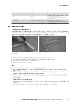
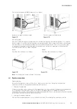
U-shaped clamp height H (mm) = pipe diameter (including insulated cotton) (mm)-5mm.
In order to reduce the vibration noise of the equipment, the following actions need to be done:
•
When the direction of the refrigerant pipeline changes, it is necessary to increase the fixed support at the
distance from the 1000 mm position where the pipeline changes.
•
When the refrigerant pipeline is a straight section, an additional fixed support is required for every 2500 mm.
ote:
N
for the fixed support, please ask the on-site engineer to be responsible for material preparation and
installation.
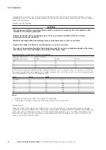
4. Connect the connection of the copper pipe between the indoor unit and the outdoor unit, and tighten the pipe
nut on the copper pipe. Torque:
φ
6 pipe nut: 15 ~ 20 N*m;
φ
9.52: 30 ~ 40 N*m;
φ
12.7: 45 ~ 55 N*m. It can
only be used as a reference value, and the installer is unlikely to use a torque wrench in practice.
5. Leak test with nitrogen.
After the copper pipe connection, open the globe valve of the indoor unit, fill nitrogen from the needle valve
before and after the expansion valve to 3.5MPa, and hold the pressure for 24 hours. The system pressure should
not be reduced under the condition that the ambient temperature is similar before and after holding pressure. If
the variable ambient temperature slightly results in pressure deviation, it is recommended to do a new pressure
retention test. After the air sealing check, please discharge the nitrogen in the system completely.
WARNING
Try not to use compressed air, as the moisture and impurities in the air will affect the work of the system.
Do not test leaks with oxygen or acetylene! Otherwise there is a danger of explosion.
6. Vacuum
Please follow the vacuum procedure.
7. Thermal insulation
Connect the copper pipe and wrap the insulation layer. The wall thickness of the heat preservation pipe is 9.25
mm and the material is rubber-plastic foam.
8. Connecting cable
Please select the cable according to the electrical connection requirements, and properly wrap and secure the
cable with plastic tape.
9. Open the gas and liquid globe valves of the outdoor unit with the inner hexagon spanner and wait 10 minutes
for the refrigerant of the outdoor unit to circulate the system.
10. Power on and start commissioning.
2.8 Installation of drain pipe
Materials to be prepared: PVC pipe, galvanized steel pipe or aluminum-plastic pipe with inner diameter of 16mm
or 4mm; external thread joint of 1/2 inch.
The unit provides condensate drain pipe connection.
1. The condensate pipe can be a choice of PVC pipe, galvanized steel pipe or aluminum-plastic pipe. The inner
diameter of self-drain pipe is 16 mm, and the inner diameter of strong drain pipe is 4 mm.
2. After connecting the drain pipe, power on and add water to the water plate (adding water from the outlet of
the drain pipe) until the low float switch is lifted to check whether the drainage is normal.
3. During the installation of the condensate pipe, there shall be no dead bend or local bending, the outlet of the
drain pipe shall not be higher than the water plate, and the radius of the bend shall not be less than 25.
4. The water pipe must be firmly connected, and there must be no shrunken pipe or strong twist.
5. The maximum lift of the pump for upper drainage is 5 meters.
6. The installation of the air conditioner must be kept horizontal, and the horizontal and longitudinal centerline
and level- ness must be corrected (to ensure that the unit is installed horizontally. If there is a inclination, it is
recommended to tilt backward, the inclination angle is less than 1 °, which is beneficial to the drainage of the
water plate), otherwise the water of the air conditioner water plate may overflow.


