DOCUMENT 1331
REV. C
Instruction Manual
PRO APF Series LED
Inset Runway Guard Light L-852G
16
the light unit lead from the isolation transformer. Clean the mounting flange area of the light base. Secure
the light to the base per Section 9.1.
10.7 Power Lead/Feed-thru Replacement
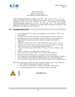
WARNING
WARNING:
The warranty is void if the screws holding the L852G optical housing to the
inner cover are loosened or removed.
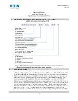
Refer to Table 1 to determine the appropriate Feed-thru replacement for your light unit.
REMOVE and
SECURE power to the light unit.
Separate the Optical Assembly from the outer ring by removing the
two bolts.
There are two pry slots in the optical housing to help separate the optical assembly from
the support ring.
Disconnect the light unit lead from the isolation transformer. Disconnect the power
supply leads from the feed-thru terminals. Remove the feed-thru by unscrewing the retaining collar. Clean
the mounting surfaces with denatured alcohol and allow them to dry. Apply a thin coat of Dow Corning
FS 1292 grease to the mounting flange of a new feed-thru. Apply a drop of Loctite 243 to the feed-thru
adapter threads. Screw the feed-thru retaining collar onto the adapter. Torque the retaining collar to
25-30
in-lbs.
Reconnect the power supply leads to the feed-thru terminals. Inspect/replace the inner cover’s
gasket per Section 10.3. Inspect/replace the optical housing’s O-ring gasket per Section 10.5. Assemble
the inner cover onto the light housing. Tighten the mounting screws to
30 in-lbs.
Perform a pressure test
as described in Section 10.10. Connect the light unit lead from the isolation transformer. Clean the
mounting flange area of the light base. Secure the light to the base per Section 9.1.
10.8 Power Supply Bluetooth Board Replacement
Refer to Table 1 to determine the appropriate Bluetooth Board replacement for your light unit.
REMOVE
and SECURE power to the light unit.
Separate the Optical Assembly from the outer ring by removing
the two bolts.
There are two pry slots in the optical housing to help separate the optical assembly
from the support ring.
Disconnect the light unit lead from the isolation transformer. Disconnect the LED
cable from the expansion board, located on top of the main power supply in the inner cover assembly. Remove
the single nut, lock washer, and washer above the expansion board, which secures the expansion board to the
power supply underneath it. Note: There are 2 spacer washers between the expansion board and the power
supply bracket. Remove the expansion board form the power supply by gently pulling the expansion board up
and away from the power supply. Discard the old expansion board as an electronics assembly. Replace the 2
spacer washers, align and engage the connectors of the new expansion board with the power supply and press
it into place. Replace the flat washer, lock washer and nut on to the mounting screw. Torque the nut to
16-18


