background image


DOCUMENT 1331 

REV. C 


Instruction Manual 

PRO APF Series LED 

Inset Runway Guard Light L-852G 


13


10.2.3  Snowplow operators should exercise extra care not to strike the light units with snowplow blades. 
 

Use rubber blades for added protection to the unit. After snow removal operations, inspect all 


light units to locate and replace, if necessary, any damaged light assemblies.  Passes over the light 


rows should be made with a power broom only if practical. Whenever snowplows must traverse 


in-pavement light units, they should be traveling at less than 5 mph or have the blades lifted clear 


of the unit. Recommended snow removal techniques are described in AC 150/5200-23. 

 
10.2.4  The light is designed to exclude both ground and surface water from entering. If the lights are not 

properly maintained (i.e., bolts tightened and seals in good condition) water may enter the unit. 
To prevent this from occurring, it is recommended that each unit be inspected for the presence of 
water at least once a month. More frequent inspection is desirable during and following rainy 
seasons. 

 
10.2.5  If any light unit contains water, the water should be removed and the entire unit cleaned and 

dried. If any of the electronics have been damaged, it may not be cost effective to make a field 
repair, but rather send it back to Crouse-Hinds Airport Lighting for rebuild.  Perform a pressure 
test per Section 10.10 to locate the source of the leak. Refer to the o-ring, lens, and power lead 
sections, 10.5, 10.6, & 10.7 as needed to make repairs. After any repair, pressure test again per 
Section 10.10. 


10.3        Cleaning Lenses 

 
With a compressed air blast or suitable brushes, remove all accumulated debris from the light channel. 
Clean the outer lens surface with a detergent solution. If the lens is coated with a substance impervious to 
the detergent, a suitable solvent should be sparingly applied with a wad of cotton or a patch of cloth on 
the end of a wood splint. After the solvent has acted, the remaining solvent and softened coating should 
be removed with a clean piece of cotton or cloth.  Care should be taken to avoid excessive contact 
between the solvent and the lens seal. Remove all remaining solvent from lens and lens seal. A gentle air 
blast may be used. It is good practice to inspect for damage to the optical housing and/or water intrusion 
into the unit anytime a lens is cleaned. Water droplets would be visible on the inside of the lens if 
moisture had entered the unit.  If it is determined that moisture has entered the unit, refer to Section 10.2.5 
for possible causes and maintenance procedures. 


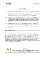
NOTICE 


NOTICE: 

The LED PCB is warm when light unit is energized and remains warm for a 

short time after unit is turned off.


Summary of Contents for L-852G

Page 1: ...ight FAA Type L 852G OR Stop Bar Light FAA Type L 852S 8 inch aluminum optical housing with ductile iron support ring Cooper Lighting Solutions Airport Lighting Products 1200 Kennedy Road Windsor CT 0...

Page 2: ...llation Guidlines 11 10 Maintenance 11 10 1 Cleanliness and Workmanship 12 10 2 Maintenance Program 12 10 3 Cleaning the Lenses 13 10 4 Replacing the LED Modeule 13 10 5 O Ring Replacement 14 10 6 Len...

Page 3: ...151 Initial Issue with ECN 10 12 20 PG C A221 076 Pg 7 Updated P N Explanation for addition of 4 option of logitrac monitoring 852GAP1 Pg 23 Added item 20 21616 6 Item 12 10035 0073 was 10035 0062 Pg...

Page 4: ...nty information f EXCEPT FOR THE EXPRESS WARRANTY SET FORTH ABOVE SELLER PROVIDES PRODUCTS AS IS AND MAKES NO OTHER REPRESENTATIONS OR WARRANTIES EXPRESS OR IMPLIED STATUTORY OR OTHERWISE REGARDING TH...

Page 5: ...azard or unsafe practice will result in severe injury or death WARNING WARNING The hazard or unsafe practice could result in severe injury or death CAUTION CAUTION The hazard or unsafe practice could...

Page 6: ...ry Circular AC 150 5340 26 for additional information 6 Recommended Test Equipment and Tools There is a wide variety of tools and equipment needed to safely and correctly perform airfield lighting equ...

Page 7: ...ime A calibrated torque wrench micrometer adjustable solid audible tactile click impulse when torque value attained with an accuracy of 4 to fit a 9 16 or 14 mm socket for drive size of the socket to...

Page 8: ...The fibers are usually made of carbon filled rubber and the strap is bound with a stainless steel clasp or plate They a usually used in conjunction with an ESD table mat on the workbench or a special...

Page 9: ...g aircraft or ground vehicles is desirable The fixture is designed to fit on a FAA L 868 steel Size B light base per FAA AC 150 5345 42 latest version and have a total height above grade ground level...

Page 10: ...t is to be done with primary POWER OFF and SECURED At each light location install a steel Size B 12 inch deep minimum L 868 Light Base per FAA AC 150 5340 4 latest revision Place the properly sized is...

Page 11: ...ed cleaned and dried prior to installation Apply marine grade anti seize K 18 per manufacturer s instructions to each bolt Install the 3 8 16 bolts with lock washers per lock washer manufacturer s gui...

Page 12: ...ensure that 2 3 threads extend beyond the nut on through bolt applications Step 2 Tighten each bolt to one third of the final required torque following the pattern as shown below Step 3 Increase the t...

Page 13: ...ould be installed per instruction in Section 9 with the primary POWER OFF and SECURED The affected light unit can be troubleshot in a clean safe working area or returned to Crouse Hinds Airport Lighti...

Page 14: ...o make a field repair but rather send it back to Crouse Hinds Airport Lighting for rebuild Perform a pressure test per Section 10 10 to locate the source of the leak Refer to the o ring lens and power...

Page 15: ...eep the new light reflector clean and free of contaminants Insert the new light reflector s alignment pins into the small hole and slot of both the LED board and heat sink beneath the board Tighten th...

Page 16: ...are two pry slots in the optical housing to help separate the optical assembly from the support ring Disconnect the fixture lead from the isolation transformer Turn the optical assembly upside down an...

Page 17: ...pect replace the optical housing s O ring gasket per Section 10 5 Assemble the inner cover onto the light housing Tighten the mounting screws to 30 in lbs Perform a pressure test as described in Secti...

Page 18: ...cement 10 9 1 Visual Inspection If a light unit is under warranty please contact Crouse Hinds Airport Lighting for assistance DO NOT open the unit If the unit is opened the warranty is VOID If the war...

Page 19: ...s See Figures 7 8 and 9 Jumpers shown in Figure 1 are for example only IMPORTANT IMPORTANT The jumpers must be placed in the correct position s for proper operation of the appropriate fixture Replace...

Page 20: ...noise coming from the isolation transformer may indicate a failed power supply or LED module It is also an indicator of dangerous voltage on the primary and secondary sides of the transformer NOTICE...

Page 21: ...ace the power supply per Section 10 9 3 or contact Crouse Hinds Airport Lighting Products for assistance 10 9 3 Power Supply Replacement CAUTION CAUTION Power supply is hot when light unit is energize...

Page 22: ...ower supply bracket using 3 10 2 piece lock washers torque the three bracket mounting screws to 25 30in lb Connect the ends of the LED cables to the expansion board Inspect the feed thru terminal for...

Page 23: ...00 positions 1 to 2 after the power supply is safely de energized after the 10 second minimum reset period 10 10 Pressure Test A light unit should be subjected to a 20 psi maximum air pressure test to...

Page 24: ...ly Red 10 21696 2 Power Supply Arctic Kit Red Power Cord Assembly 11 K3326992 Lead Assembly Seal Bottom Cover 12 10035 0073 O Ring 2 Piece Lock Washer Kit 13 21647 2 2 Piece Washer Replacement Kit QTY...

Page 25: ...able 2 21716 XX bolt lengths P N Length IN P N Length IN 21716 07 0 88 21716 22 2 75 21716 08 1 00 21716 24 3 00 21716 09 1 13 21716 26 3 25 21716 10 1 25 21716 28 3 50 21716 11 1 38 21716 32 4 00 217...

Page 26: ...DOCUMENT 1331 REV C Instruction Manual PRO APF Series LED Inset Runway Guard Light L 852G 25 12 Tables and Figures Figure 4A Part Layout P1 Option...

Page 27: ...DOCUMENT 1331 REV C Instruction Manual PRO APF Series LED Inset Runway Guard Light L 852G 26 Figure 4B Installation View of Inner Cover P2 option...

Page 28: ...DOCUMENT 1331 REV C Instruction Manual PRO APF Series LED Inset Runway Guard Light L 852G 27 Figure 5 19999 Installation Lifting Tool TCL Fixture Shown...

Page 29: ...F Series LED Inset Runway Guard Light L 852G 28 Figure 6 WIRING DIAGRAM FIGURE 7 PART NUMBER 852SAP1 RN NF XX X STOP BAR POWER SUPPLY J203 JUMPER CONFIGURATION FIGURE 8 FIRST ON YO POWER SUPPLY J203 J...

Page 30: ...TAGE USED WITH LOGITRAC RECOMMENDED TRANSFORMER SIZE L 852G UNIDIRECTIONAL YELLOW 852GAP1 YN YO __ _ FIGURE 8 30 7 No 30 45W Yes 65W L 852G UNIDIRECTIONAL YELLOW 852GAP1 YN YO __ 3 FIGURE 8 30 7 No 10...

Page 31: ...DOCUMENT 1331 REV C Instruction Manual PRO APF Series LED Inset Runway Guard Light L 852G 30 Figure 10 WIRING DIAGRAM Figure 11 WIRING DIAGRAM...

Page 32: ...DOCUMENT 1331 REV C Instruction Manual PRO APF Series LED Inset Runway Guard Light L 852G 31 Figure 12 WIRING DIAGRAM Figure 13 WIRING DIAGRAM...

Page 33: ...Android based application that can be used to configure light fixtures as well as to gather diagnostic information about the fixtures Section 13 1 provides user instructions for running the app 13 1...

Page 34: ...ures The Configuration App has two features Diagnostics and Configuration The Diagnostics feature can be used to gather data about the fixture while the configuration feature can be used to configure...

Page 35: ...FF Whether the fixture starts blinking as first on or first off can be changed by clicking SET FIRST ON or SET FIRST OFF button The change will take effect the next time the light fixture is turned on...

Page 36: ...3 Change Ramp Time The ramp time of the fixture can be changed by clicking DECREASE RAMP or INCREASE RAMP 13 1 3 4 Toggle Blinking Blinking can be toggled by clicking the TOGGLE BLINKING button Click...

Page 37: ...cs feature tap on Diagnostics 13 1 4 1 Operating Data The following data is displayed under Operating Data Input Current Current Step PFC Voltage LED Voltage LED Current 12V Bias Voltage Line Frequenc...

Page 38: ...13 1 4 3 Operating Hours The following data is displayed under Operating Hours Total Hours B1 Hours B2 Hours B3 Hours B10 Hours B4 Hours B30 Hours B5 B100 Hours 13 1 4 4 Error Logs The following data...

Page 39: ...DOCUMENT 1331 REV C Instruction Manual PRO APF Series LED Inset Runway Guard Light L 852G 38 13 1 5 Help The help screen displays helpful information about the Configuration App...

Reviews: