DOCUMENT 1331
REV. C
Instruction Manual
PRO APF Series LED
Inset Runway Guard Light L-852G
9
strength shear pins. The aluminum housing has a die cast bottom housing that is attached using 4
screws. A polyurethane O-ring is used to provide a watertight seal between the inner cover and
the optical housing. Electrical connections are made at one feed-thru assembly in the inner cover.
The feed-thru have ITS verified L-823 plugs for connecting to FAA L-830/ L-831 Isolation
Transformers. Lenses are held into the aluminum housing with a bracket, gasket, molded
elastomeric boot and two screws. The yellow light beam color is produced using white LED’s and
optics with a dichroic coating on the lenses All hardware is type 18-8 stainless steel. The
complete light unit is 11.94 inches in diameter, 5.00 inches deep and weighs 25 lbs. All units
leave the factory pressure tested. if the unit is serviced during its lifetime, it must be re-tested to
ensure it remains waterproof.
IMPORTANT
IMPORTANT:
Do not open any fixture unless the warranty period has expired.
Opening a fixture will void the warranty
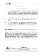
CAUTION
CAUTION:
Never handle the light assembly by the leads as this can break the
waterproof seal
9 Installation
The Style 3 IRGL units are shipped complete, including the LED module(s), and are ready for
installation as received.
Installation of a light unit is to be done with primary POWER OFF
and SECURED.
At each light location, install a steel, Size B, 12 inch deep minimum, L-868
Light Base per FAA AC 150/5340-4 (latest revision). Place the properly sized isolation
transformer(s) in the light base and make necessary primary power connections using L-823
connectors.
Isolation transformer requirements are dependent on a light unit’s heater option and
whether it is used with a Logitrac device. All isolations transformers are 6.6 ampere secondary
models. Verify that the mounting flange on the light base is clean and the O-ring (optional on
deep cans) is coated with Dow Corning FS 1292 grease and is in place on the light base. Connect
the plug(s) from the light unit to the secondary of the previously installed isolation transformer(s).
Installation tool, Crouse-Hinds P/N 19999, will ease in the installation and removal of the light
unit (See Figure 4A). The threaded eyebolts on the lifting tool screw into threaded holes in the
light fixture. Lower the light unit straight down onto the base. The light fixture is subject to
optical misalignment or mechanical damage if not seated properly. Verify the light beam is
properly orientated for the individual location. Secure the light unit to the base per section 9.1.
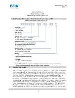
All 852G-AP1 light units are flashing lights. For light units with the “YO” designator in the part
number, the light will flash ON first in the cycle. For light units with the “YF” designator in the
part number, the light will flash OFF first in the cycle. This allows the light installers to arrange


