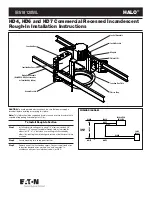
HALO
®
Instructions For Vertical Adjustment Of The Downlights
Instructions For Use Of Indicator
(Use On HD4 Housings)
Step 1
Loosen wingnuts located on vertical legs of fixture. (Fig 3)
Step 2
Identify lamp/trim combination to be installed on indicator (indicator
included with fixture and trim).
Step 3
Properly locate top edge of indicator (arrow up) under the socket
bracket (as shown).
Step 4
Position socket assembly to proper lamp/trim mark on indicator
(Mark should be even with ceiling line). Tighten wingnuts securely.
Step 5
Insert trim and tighten trim retaining screws within the socket cap.
Instructions For Use Of Indicator
(Use On HD6 And HD7 Housings)
Step 1
Loosen wingnuts located on vertical legs of fixture. (Fig 4)
Step 2
Identify lamp/trim combination to be installed on indicator (indicator
included with fixture and trim).
Step 3
Properly locate top edge of indicator (arrow up) under the lower
edge of socket bracket (as shown).
Step 4
Position socket assembly to proper lamp/trim mark on indicator
(Mark should be even with ceiling line). Tighten wingnuts securely.
Step 5
Insert trim and tighten trim retaining screws within the socket cap.
Wall Wash Reflector Adjustment
Insert top of reflector into socket housing. Push reflector upward to allow reflec-
tor mounting screws to pass thru keyslots in reflector. Rotate reflector slightly to
captive position. Tighten screws until trim ring or flange is adjusted to ceiling line.
Reflector mounting screws are factory installed for most Wall Wash reflector in-
stallations. If additional adjustment is required, refer to the following
instructions:
Step 1
If additional adjustment is required, (2) additional reflector mounting
screws are included. These can be installed in any of the additional
mounting bracket holes. The holes are 15˚ apart. If the additional (2)
screws are used, be sure to insert the factory installed screws
completely. (Fig 5)
Step 2
If only fine adjustment is required loosen bracket adjustment screws,
this slot will allow for up to 15˚ of adjustment, retighten screws when
in proper position.
Wall Wash reflectors can be used for various lighting applications. For proper
orientation, refer to Fig 6.
To Clean Trims
Step 1
Gently wipe with a soft, clean, dry lint-free cloth to remove dust.
Step 2
Wipe with a mild detergent solution on a soft, clean cloth to remove
fingerprints and stains.
Step 3
Rinse with clean, soft water and dry with lint-free cloth.
Wingnut
Socket Bracket
Ceiling Line
Ceiling Line
Locate
Indicator
At Bracket
As Shown
Indicator
4" Plaster Ring
FIG 3
Ceiling Line
Ceiling Line
Wingnut
Socket Bracket
Locate Indicator
At Socket Bracket
As Shown
Indicator
6" Plaster Ring
Wingnut
FIG 4
Bracket Adjustment Screws
Reflector
Mounting
Bracket
Socket Housing
Reflector Mounting
Screw
Looking Into Socket Housing
15˚
150˚
120˚
90˚
90˚
30˚
30˚
150˚
120˚
60˚
60˚
FIG 5
Single Wall Wash
Double Wall Wash
Corner Wall Wash
FIG 6 Wall Wash Diagram
Socket Assembly
Socket Assembly
Wingnut
Wingnut
Indicator
Indicator
4" Plaster
Ring
6" Plaster
Ring
Ceiling
Cut-away
Ceiling Line
Ceiling Line
Socket
Bracket
Socket
Bracket
HD4 Housings
HD6 And HD7 Housings


