


53
645M 4G/LTE CELLULAR ROUTER
MN032003EN March 2017 www.eaton.com
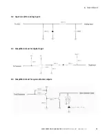
6.1 Electrical characteristics
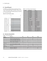
6 User I/O port
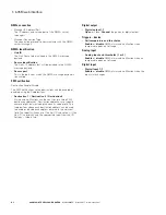
The 645M has a 22 pin connector on the back panel that can
be used for general purpose analog and digital inputs as well
as open collector digital outputs. The signals listed in the User
I/O Port Connector Pin Out Table are available, and the electrical
characteristics are defined in the following section. All unused
pins should be left floating.
Figure 54 . User I/O port connector
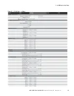
Table 9 . User I/O port connector pin out
Pin number
Signal Name
Notes
1
DIGITAL INPUT1
Digital input
2
DIGITAL INPUT2
Digital input
3
DIGITAL INPUT3
Digital input
4
DIGITAL INPUT4
Digital input
5
DIGITAL INPUT5
Digital input
6
DIGITAL INPUT6
Digital input
7
DIGITAL INPUT7
Digital input
8
1BB_1_DATA
One bit bus
9
GND
GND
10
1BB_2_DATA
One bit bus
11
GND
GND
12
DIGITAL OUTPUT0
Open collector output
13
DIGITAL OUTPUT1
Open collector output
14
DIGITAL OUTPUT2
Open collector output
15
DIGITAL OUTPUT3
Open collector output
16
DIGITAL OUTPUT4
Open collector output
17
OUT_LED1
LED Driver
18
OUT_LED2
LED Driver
19
Analog input 1
Analog input/HW ADC2
20
Analog input 2
Analog input/HW ADC3
21
Analog input 3
Analog input/HW ADC4
22
Analog input 4
Analog input/HW ADC5
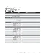
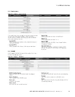
Table 10 . External connectors
Symbol
Parameter
Min
Typ
Max
Units
Digital Inputs
V
IN
Digital Voltage Recommended Input Range
0.0
30.0
V
V
P
Positive Threshold Voltage for Digital Inputs
3.1
3.4
V
V
N
Negative Threshold Voltage for Digital Inputs
2.8
3.1
V
V
H
Hysteresis Voltage for Digital Inputs
0.07
0.1
V
Analog Inputs
V
IN
Analog Voltage Recommended Input Range
0.0
30.0
V
Accuracy
ADC accuracy
+/- 2%
+/-5%
V
Digital Outputs
Iout
Drive current for Relay Outputs
200
mA
Iout
Drive Current for LED Outputs
20
mA
6 User I/O port