3 Installation
3.5 EMC installation
58
DC1-S…20…, DC1-S…OE1 Variable Frequency Drives
05/21 MN040058EN
www.eaton.com
3.5.2.2 Motor earthing
The motor earthing must be connected to one of the earthing terminals on
the variable frequency drive, as well as to the central earth point on the
power drive system (PDS). Earth connections to a neighboring steel element
in the building (e.g., beam, ceiling joist), a ground rod in the ground, or a
mains earth bus must meet the requirements set forth in the applicable
national and regional industrial safety regulations and/or regulations for
electrical systems.
3.5.2.3 Earth-fault protection
A fault current to earth can be produced by variable frequency drives due to
their system characteristics. DC1-S… variable frequency drives have been
designed in such a way that the smallest possible fault current will be
produced in compliance with standards applicable worldwide.
3.5.3 Internal filters (EMC and VAR screws)
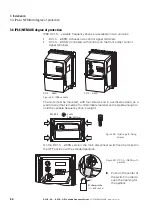
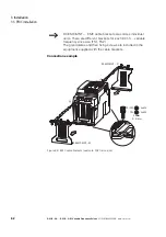
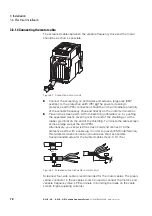
FS1 and FS2 DC1-S… variable frequency drives with an IP20 degree of
protection feature two screws on the left side that are labeled EMC and VAR.
Figure 34: EMC and VAR screw
3.5.3.1 EMC screw
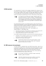
Due to their system characteristics, variable frequency drives with an internal
EMC filter will produce a larger fault current to earth than devices without a
filter.
PH1
M3
20 mm
(0.79")
EMC
EMC
L3
L2/N
L1/L
NOTICE
The screw labeled EMC must not be manipulated as long as the
variable frequency drive is connected to the mains or there is a
DC link voltage.
→
The EMC screw galvanically connects the EMC filter’s mains-
side capacitors to the earthing (PE). The screw must be
screwed in all the way to the stop (factory setting) in order for
the variable frequency drive to comply with EMC standards.
Summary of Contents for DC1-S1011NB-A20CE1 1
Page 4: ......


