IB01602002E
Effective October 2002
Cutler-Hammer
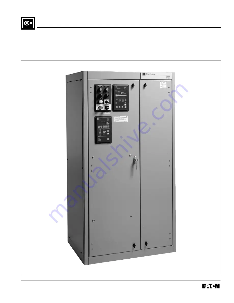
O & M Manual for Cutler-Hammer Fixed SPBTransfer Switch
BCS Switchgear Inc.
Switchgear | Circuit Breakers | Parts | Tech Support
bcsswitchgear.com | 888.599.0486
Need Help? 888.599.0486
Page 1: ...Effective October 2002 Cutler Hammer O M Manual for Cutler Hammer Fixed SPB Transfer Switch BCS Switchgear Inc Switchgear Circuit Breakers Parts Tech Support bcsswitchgear com 888 599 0486 Need Help 8...
Page 2: ...BCS Switchgear Inc Switchgear Circuit Breakers Parts Tech Support bcsswitchgear com 888 599 0486 Need Help 888 599 0486...
Page 3: ...NT NAMEPLATE IS SHOWN IN FIGURE 1 Figure 1 Typical Automatic Transfer Switch Equipment Nameplate Cutler Hammer Automatic Transfer Switch E Cat No ATVISPA32000XSU 10 02 GO No 1 of 1 Item 1 Poles 3 Amps...
Page 4: ...PMENT DESCRIPTION 3 1 General 6 3 2 Power Panel 6 3 2 1 Main Contacts 6 3 2 2 Interlocks open transition only 6 3 2 3 Load 7 3 2 4 Transfer Mechanism 7 3 3 Voltage Selection Panel 8 3 4 Logic Panel 8...
Page 5: ...RTS GUIDE 8 1 General 28 LIST OF FIGURES Figure Title Page 1 1 Typical Load Transfer Switch circuit breaker type Schematic 2 1 2 Typical Mini Transfer Switch with Dead Front Attached 3 1 3 Typical Min...
Page 6: ...ulling Cover Out 25 7 10 Cover Against Frame 26 7 11 Inserting Tabs into Screw Holes 26 7 12 Sliding Cover Flange Under Roof Flange 26 7 13 Pushing Bottom of Cover in Place 27 7 14 Replacing Screws an...
Page 7: ...E WARNINGS AND CAUTIONS INCLUDED AS PART OF THE PROCEDURAL STEPS IN THIS DOCU MENT ARE FOR PERSONNEL SAFETY AND PRO TECTION OF EQUIPMENT FROM DAMAGE AN EXAMPLE OF A TYPICAL WARNING LABEL HEAD ING IS S...
Page 8: ...Transfer Switch Electrically Operated Non Automatic Transfer Switches are manually initiated electrically operated devices for applications where automatic load transfer is not required 1 2 2 DESIGN...
Page 9: ...kA kA Fuse Rating Type kA 600 No 85 65 25 800 1200 L 200 800 No 85 65 25 1200 1600 L 200 1000 No 85 65 25 1600 L 200 1200 No 85 65 25 2000 L 200 800 Yes 100 100 85 1200 1600 L 200 1000 Yes 100 100 85...
Page 10: ...e Table 1 2 provides the required interpretation information for both closed and open tran sition switches An example for an open transition switch is offered initially to simplify the process Example...
Page 11: ...not discard the packing material until the equipment is ready for installation A plastic bag of documents will be found within the enclosure usually attached to the inside of the door Important docume...
Page 12: ...e installed in accordance with the specific requirements of the circuit being controlled Each transfer switch is therefore tailor made to a specific application 3 2 POWER PANEL The power panel consist...
Page 13: ...e switches with a stored energy mechanism An electrical operator automatically recharges the mechanism after the switch ing device has been closed An indicator on the switch shows whether it is in the...
Page 14: ...ate document ATC 600 Instruction Book open transition only ATC 800 Instruction Book closed transition only 3 5 NEUTRALS All 2 pole and 3 pole transfer switches are equipped with 100 percent rated neut...
Page 15: ...xed mounted SPB type transfer switch es 800A 1200A 18 Metering and Communications The IQ Family of microprocessor based multi function monitoring and display devices features the latest tech nological...
Page 16: ...ecial lengths are available Contact Cutler Hammer 37 Service Entrance Rated Transfer Switch Provides the label Suitable for use as Service Equipment and the features necessary to meet the requirements...
Page 17: ...Electrical Code ANSI NFPA 70 and the National Fire Protection Association No 76A and or b In stand by systems in accordance with article 702 of the National Electrical Code and or c In legally requir...
Page 18: ...routed to retard the action of relays or cover the logic in a way that restricts adjustments Maintain proper electrical clearances between live metal parts and grounded metal For installation and main...
Page 19: ...late on the intelli gence panel of transfer switch agree with sys tem current and voltage Step 3 After the transfer switch is mounted provide conduit or cable openings as required Ensure that no metal...
Page 20: ...connected to locations as indicated in the Customer Wiring Diagrams supplied with the transfer switch equipment 4 7 1 ENGINE START CONNECTION The engine control contact connections are located on the...
Page 21: ...d Product Mounting Instructions In all cases the unit must be mounted per the outline drawing In addition the floor mounted units must use the provided cleats These cleats must be placed between the h...
Page 22: ...ton Figure 5 2 The other switching device is pre vented from closing through a rigid mechanical interlock Paragraph 3 2 2 An indicator window shows whether the switch is open or closed If a transfer s...
Page 23: ...EACH SWITCHING DEVICE WARNING Manual Operation Instructions 1 Disconnect Logic Connectors 2 Open both switching devices 3 Verify OPEN flags 4 Verify source availability 5 Close switching device on av...
Page 24: ...Y VOLTAGE SOURCE WHILE PROBLEM SOLV ING ONLY PROPERLY TRAINED PERSONNEL FAMILIAR WITH THE TRANSFER SWITCH EQUIPMENT AND ITS ASSOCIATED EQUIPMENT SHOULD BE PERMIT TED TO PERFORM THE PROBLEM SOLVING FUN...
Page 25: ...RANSFER SWITCH WILL NOT AUTOMATI CALLY TRANSFER TO NORMAL Step 1 Check for proper line voltage on N1 N2 N3 Step 2 Is the normal switching device charged If YES Continue with other procedures If NO Go...
Page 26: ...n emergency switch If NO Check wiring to A1 and A2 6 2 4 TRANSFER SWITCH WILL NOT AUTOMATI CALLY RECHARGE SWITCHES Step 1 Measure the voltage between the terminals A6 and A2 on the switching device th...
Page 27: ...bility of application conditions and the importance placed on dependable operation by this type of equipment inspection and maintenance checks should be made on a regularly scheduled basis Since equip...
Page 28: ...n grease moisture or corrosion contamination from the surface of the switching device using a dry soft lint free cloth dry soft bristle brush and vacuum cleaner Do not blow debris into circuit breaker...
Page 29: ...a double doors Side access is not provided 7 3 1 NEMA 1 COVER REMOVAL AND REPLACEMENT A 3 8 wrench is required to perform this procedure Cover Removal Step 1 Locate the screws used to secure the cover...
Page 30: ...place with your foot Step 2 Move your hands around to the front and push the cover fully into the enclosure frame Figure 7 5 Step 3 Replace the cover screws taking care not to cross thread the screws...
Page 31: ...ng washers remain on the screws during removal Step 2 Locate the cover lifting handles provided with the equipment and insert the tabs into the screw holes Figure 7 8 Step 3 Grasp the cover lifting ha...
Page 32: ...e upper cover flange under the roof flange Figure 7 12 When the lower cover flange clears the top of the lower cross member push the bottom of the cover in place Figure 7 13 Step 4 Replace the cover s...
Page 33: ...IB01602002E Page 27 Effective 10 02 Figure 7 13 Pushing Bottom of Cover in Place Figure 7 14 Replacing Screws and Sealing Washers Slide Up Under Roof Flange Push In Place...
Page 34: ...ng and ordering selected transfer switch renewal parts Example To order the Air Filter Replacement Kit for an ATVISPB31200XRU transfer switch order Catalog Number TSAFFM as shown in Figure 8 1 Figure...
Page 35: ......
Page 36: ...contract between the purchaser and Cutler Hammer NO WARRANTIES EXPRESSED OR IMPLIED INCLUDING WARRANTIES OF FITNESS FOR A PAR TICULAR PURPOSE OR MERCHANTABILITY OR WARRANTIES ARISING FROM COURSE OF DE...