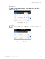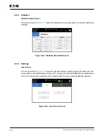
background image

Eaton 93PR 60-1200 kW UPS

Installation and Operation Manual

109

Copyright © 2021 Eaton Corporation plc. All rights reserved.

3.  Unfasten the front door latch and swing the door open.
4.  (If the UPS contains) Close the UPS output switch, bypass switch, and close the front door.
5.  Repeat steps 3-5 for all UPSs in the system.

6.3.8.    De-energizing the Critical Load

A UPS system Load Off is initiated by the

 Load Off

 button 

from Controls

 > 

System Controls


screen. This button can be pressed to control the UPS output. The 

Load Off 

button de-energizes 

the critical load and

Powers down the UPS system.

The UPS system (including Bypass) remains off until restarted.

1. 

Press 

Load Off

.

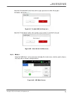
The shut down screen appears, providing a choice to proceed or abort the shutdown.

         NOTE

All power to the critical load is lost when Load Off is selected in the following step. You 

should use this feature only when you want to de-energize the critical load.

2.  To shut down the UPS, press 

Load Off

. To abort the shutdown, press ABORT. When 

Load 

Off

 is selected, the input, output, and bypass backfeed contactors open, the battery breaker 

or disconnect is tripped, and all the UPSs in the system are turned off.

          DANGER

Power is present inside the UPS cabinet until the upstream input feeder circuit breaker is 

opened.

3.  To restart the UPS system, follow the procedure in 

Section

 6.3.1 

Starting the UPS System in 

Double Conversion Mode

 or Section


6.3.2 

Starting the UPS System in Bypass Mode.

Summary of Contents for 93PR Series

Page 1: ...60 1200 kW Installation and Operation Manual Eaton 93PR UPS ...

Page 2: ......

Page 3: ...tions specified in the manual and on the equipment and keep the manual properly for future reference Do not try to operate the equipment before reading all the safety information and operation instructions The manual applies to the 93PR series including 93PR 300 93PR 600 93PR 1200 ...

Page 4: ...nual are the copyright of the publisher and may not be reproduced even extracts without the written approval of Eaton Corporation Every care has been taken to ensure the accuracy of the information contained in this manual but no liability can be accepted for any errors or omission The right to make design modifications is reserved All Rights Reserved WARNING This is a product for commercial and i...

Page 5: ...nnectivity Features 22 2 4 1 Customer Interface 22 2 4 2 Power Management Software 22 2 5 Options and Accessories 22 2 5 1 Field Installed UPM 22 2 5 2 External Battery Cabinet EBC 23 2 5 3 Eaton Sync Control Sync Control 23 2 5 4 Top Exhaust Accessory 23 2 6 Battery System 23 2 7 Basic System Configurations 24 Chapter 3 UPS INSTALLATION PLAN AND UNPACKING 25 3 1 Creating an Installation Plan 25 3...

Page 6: ...talling Customer Input Signals Interface 70 4 10 2 External Battery Breaker Wiring Interface 70 4 10 3 Relay Output Interface Connections 71 4 10 4 Mini slot Interface Connections 71 4 10 5 Installing Signal Interface Connections In Parallel System 71 4 11 Wiring Parallel 93PR UPS Systems 72 4 11 1 Power Wiring Overview 72 4 11 2 Control Signals Overview 76 4 11 3 Installing Bypass Control Wiring ...

Page 7: ...the Battery Charger 111 6 5 UPM Control Instructions 111 6 5 1 Adding Reducing Replacing Modules Online 111 6 5 2 Starting the UPMs 114 6 5 3 UPM Shutdown 114 6 6 Using the Remote Emergency Power off switch 115 6 7 Transfer the UPS from Double Conversion Mode to Maintenance Bypass Mode 116 6 8 Transfer UPS from Maintenance Bypass to Double Conversion Mode 117 Chapter 7 UPS MAINTENANCE 118 7 1 Impo...

Page 8: ...g Tabs 44 Figure 4 5 Fork into Position 44 Figure 4 4 Remove the Shipping Bracket 44 Figure 4 2 Remove Wooden Box 44 Figure 4 3 Remove Cushioning 44 Figure 4 6 Instruction for Removing the UPM Module Packaging 45 Figure 4 7 Instruction for Removing the Top Exhaust Accessory Packaging 46 Figure 4 8 Lifting diagram schematic 47 Figure 4 9 Gland Plate and Connector Locations Rear Exhaust 49 Figure 4 ...

Page 9: ...Input Meters Screen 92 Figure 6 11 Bypass Meters Screen 93 Figure 6 12 Output Meters Screen 93 Figure 6 13 Input Meters Detail Screen 94 Figure 6 14 Online Mode Metering Method Option Screen 94 Figure 6 15 Select Source Screen 94 Figure 6 16 Battery Meters Screens 95 Figure 6 17 Battery Voltage Screens 95 Figure 6 18 Battery Current Screens 95 Figure 6 19 System Controls Screen 96 Figure 6 20 UPS ...

Page 10: ... 40 Configuration Options Screen 105 Figure 6 41 Prompt for level 3 Password Screen 105 Figure 6 42 UPM Module Location 113 Figure 6 43 Double Conversion Mode 116 Figure 6 44 Maintenance Bypass Mode 116 Figure 6 45 Maintenance Bypass Mode 117 Figure 6 46 Double Conversion Mode 117 Figure 7 1 WEEE Symbol 120 Figure 7 2 Recycling Batteries Symbol 120 ...

Page 11: ...A 39 Table 3 8 UPS Power Cable Terminations 40 Table 4 1 Signal Cables Connection Between the Primary Cabinet and the Secondary Cabinet 57 Table 4 2 Signal Cables Connection of Top Exhaust Accessories 58 Table 4 3 Signal Cables Connection of Sync 59 Table 4 4 Normally Open REPO Connections and Wire Terminations 68 Table 4 5 Normally Closed REPO Connections and Wire Terminations 69 Table 4 6 Dry Co...

Page 12: ...VICEABLE PARTS inside the UPS WARNING The UPS is powered by its own energy source batteries The output terminals may be energised even when the UPS is disconnected from an AC source To reduce the risk of fire or electric shock install this UPS in a temperature and humidity controlled indoor environment free of conductive contaminants Ambient temperature must not exceed 40 C 104 F Do not operate ne...

Page 13: ...oor closed and front panels installed to ensure proper cooling airflow and to protect personnel from dangerous voltages inside the unit Do not install or operate the UPS system close to gas or electric heat sources The operating environment should be maintained within the parameters stated in this manual Observe all DANGER CAUTION and WARNING notices affixed to the inside and outside of the equipm...

Page 14: ...onal connectivity modules and their software The user must follow the precautions and only perform the described operations Any deviation from the instructions could be dangerous to the user or cause accidental load loss WARNING The user is not permitted to open any screws excluding connectivity plates and the MBS locking plate Failure to recognise the electrical hazards could prove fatal CAUTION ...

Page 15: ...mportant concepts in discussions key terms in procedures and menu options or represents a command or option that you type or enter at a prompt RISK OF ELECTRIC SHOCK Indicates that a risk of electric shock is present and the associated warning should be observed CAUTION REFER TO OPERATOR S MANUAL Refer to your operator s manual for additional information such as important operating and maintenance...

Page 16: ...ery cabinet and options or accessories installed UPM Universal power module STS Static transfer switch CM communication module HMI Human Machine Interface EPO switch Emergency Power Off switch MBS Maintenance Bypass Switch REPO Remote Emergency Power Off EAA Energy Advanced Architecture ESS Energy Saver System VMMS Variable Module Management System ABM Advanced Battery Management IO cabinet Cabine...

Page 17: ...rature range is from 20 to 25 ºC WARNING Hydrogen and oxygen gases are emitted from batteries into the surrounding atmosphere during charge float charge heavy discharge and overcharge Explosive gas mixture may be created if the hydrogen concentration exceeds 4 by volume in air Necessary air flow rate for ventilation of UPS location must be ensured 1 5 For More Information Address any inquiries abo...

Page 18: ...tomized power system solution Each UPS cabinet provides a system static bypass The output power depends on the number of power modules UPM installed inside but cannot exceed the maximum power limit of the system static bypass The power rating of a single UPS is determined by the number of UPM but the maximum power could not exceed the static bypass rating For product models see Table 8 1 A UPM inc...

Page 19: ...ight 2021 Eaton Corporation plc All rights reserved 600 kW UPS Cabinet Rear Exhaust 600 kW UPS Cabinet Top Exhaust 300 kW UPS Cabinet Rear Exhaust 300 kW UPS Cabinet Top Exhaust 1200 kW UPS Cabinet Rear Exhaust 1200 kW UPS Cabinet Top Exhaust Figure 2 1 Eaton 93PR UPS ...

Page 20: ...s Switch MBS 3 Bypass Switch 4 Communication and Control Module 5 Static Transfer Switch STS 6 Universal Power Podule UPM 7 Output Switch 8 Input Switch 9 Top Exhaust Accessory 10 I O cabinet side car Only when the bottom entry or Top Exhaust Accessory are required the side car needs to be configured Figure 2 2 Components Layout 300 kW ...

Page 21: ... 1 2 3 4 5 6 7 8 9 10 1 Top Exhaust Accessory 2 Universal Power Podule UPM 3 Communication Module CM 4 Input Switch 5 Bypass Switch 6 Maintenance Bypass Switch MBS 7 Output Switch 8 Machine Control Unit MCU 9 Static Transfer Switch STS 10 Baffle Plates These accessories are only for the top exhaust system Figure 2 3 Components Layout 600 kW ...

Page 22: ...t Secondary Cabinet UPM Cabinet 4 5 6 7 1 Top Exhaust Accessory 2 Universal Power Podule UPM 3 Fuses for Top Exhaust Accessories 4 Communication Module CM 5 Machine Control Unit MCU 6 Static Transfer Switch STS 7 Baffle Plates These accessories are only for the top exhaust system Figure 2 4 Components Layout 1200 kW ...

Page 23: ...ion Manual 11 Copyright 2021 Eaton Corporation plc All rights reserved 1 2 3 4 1 Positioning Lock 2 Cold start Button 3 Status Indicator 4 Position Lock For a description of the Status Indicator functions seeTable 6 1 Figure 2 5 Components Layout UPM ...

Page 24: ...e the status of the other UPMs 93PR 300 kW UPS includes a 300 kW rated static bypass module maximum five n internal paralleled UPM modules Configurable rectifier input switch output switch internal maintenance bypass switch and bypass switch These units do not include internal batteries For the structure diagram of the 300kW UPS cabinet please refer toFigure 2 6 93PR 600 kW UPS includes a 600 kW r...

Page 25: ...Eaton 93PR 60 1200 kW UPS Installation and Operation Manual 13 Copyright 2021 Eaton Corporation plc All rights reserved Figure 2 6 93PR 300kW UPS Wiring Diagram ...

Page 26: ...14 Copyright 2021 Eaton Corporation plc All rights reserved Figure 2 7 93PR 600kW UPS Wiring Diagram ...

Page 27: ...Eaton 93PR 60 1200 kW UPS Installation and Operation Manual 15 Copyright 2021 Eaton Corporation plc All rights reserved Figure 2 8 93PR 1200 kW UPS Wiring Diagram ...

Page 28: ...harging current for the battery if needed In Energy Saver System ESS mode the critical load is supported securely by utility power through static bypass switch with double conversion available on demand with typically less than a 2 milliseconds transition time should any abnormal condition be detected in the utility When operating in ESS mode the load is protected with inherent surge suppression O...

Page 29: ...IGBT devices and pulse width modulation PWM to produce a regulated and filtered AC output If the utility AC power is interrupted or is out of specification the UPS automatically switches to Battery Mode to support the critical load without interruption When utility power returns the UPS returns to Double Conversion Mode automatically If the UPS suffers inverter overload exceed the allowance timer ...

Page 30: ...the UPS switches to double conversion and continues to supply the critical load through its inverter In case of a complete utility outage or if input power is outside the tolerances of the system the UPS transfers to Battery Mode and continues to supply conditioned clean power to the critical load When operating in ESS the UPS superior detection and control algorithms continuously monitor incoming...

Page 31: ...rter The input relay K1 opens and the UPS output is powered from batteries through the inverter As the inverter operates uninterrupted through the transition the load remains supported continuously without disturbance If the UPS static bypass is supplied from the same source as the UPS rectifier the backfeed protection contactor K5 also opens The opening of K1 and K5 prevent system voltages from b...

Page 32: ...e display The UPS status indicated on the display is On Bypass Figure 2 12 shows the path of electrical power through the UPS system when operating in Bypass Mode NOTE The critical load is not protected while the UPS is in Bypass Mode Figure 2 12 Path of current through the UPS in Bypass Mode In Bypass Mode the output of the system is provided with three phase AC power directly from the system inp...

Page 33: ... battery charger enters float stage and the charger is operating in constant voltage mode Rest mode begins at the end of charge mode that is after 48 hours of float charging customer adjustable In Rest mode the battery charger is completely turned off The battery system receives no charge current during this rest period of about 28 days customer adjustable During Rest mode the open circuit battery...

Page 34: ...ic adjusting the UPM active and idle 2 4 Software and Connectivity Features 2 4 1 Customer Interface Mini Slot Communication Bays there are three communication bays for mini slot connectivity cards Mini slot cards are quickly installed and are hot pluggable See Chapter 5 for additional information 2 4 2 Power Management Software Intelligent Power software products offer tools for monitoring and ma...

Page 35: ... reference each system provides bypass sensing voltage and output critical load bus voltage to the Eaton Sync Control box For details see 4 11 4 and Table 4 3 2 5 4 Top Exhaust Accessory The top exhaust accessories are Symmetric uniformly distributed on the upper rear of the cabinet take care of the heat dissipation of UPM cabinet and IO cabinet change the airflow direction inside the cabinet so t...

Page 36: ... optional UPS options and the models where they apply Table 2 1 Standard and Optional UPS Options 300 kW 600 kW 1200 kW Smart touch screen display for system control and monitoring Standard Standard Standard SNMP web interface See Section 5 1 Option Option Option Internal MBS Standard Internal Standard Internal Rectifier input switch Option Option UPS output switch Bypass switch Integrated backfee...

Page 37: ... apply to the system being installed Use the procedures and illustrations in Section 3 2 and Chapter 4 to create a logical plan for installing the system 3 2 Site Preparations For the UPS system to operate at peak efficiency the installation site should meet the environmental parameters outlined in these instructions If the UPS needs to be operated at an altitude higher than 1000 m contact your se...

Page 38: ...emes will also create reliability concerns for any servers that are exposed to them The UPS system installation must meet the following guidelines The system must be installed on a level floor suitable for computer or electronic equipment The floor must be suitable for heavy weight and wheeling The system must be installed in a temperature and humidity controlled indoor area free of conductive con...

Page 39: ...net in both of these situations are shown in Table 3 2 Table 3 2 UPS Cabinet Minimum Clearances Rear Exhaust Clearance Top Exhaust Clearance From Top of Cabinet D1 300 mm 800 mm From Front of Cabinet D2 1000 mm 1000 mm From Back of Cabinet D3 800 mm 600 mm Cabling may require more space Service space when the two sides are not against other cabinets the 300kW top air configuration UPS can be insta...

Page 40: ...e reduction of the battery life For example if the UPS working environment temperature is 35 C the load must be less than 88 If it exceeds 90 the UPM will shut down Recommended Operating Range from 20 C to 25 C Maximum Relative Humidity 95 non condensing The room where the UPS is placed must meet the following air circulation requirements For 300KWUPS air flow need be not lower than 3400M3 h For 6...

Page 41: ... kW UPS Installation and Operation Manual 29 Copyright 2021 Eaton Corporation plc All rights reserved Top View Front View Right View Bottom View Figure 3 2 UPS Dimensions 300kW Rear Exhaust Dimensions are in millimetres ...

Page 42: ...30 Copyright 2021 Eaton Corporation plc All rights reserved Top View Front View Right View Bottom View Figure 3 3 UPS Dimensions 300kW Top Exhaust Dimensions are in millimetres ...

Page 43: ... kW UPS Installation and Operation Manual 31 Copyright 2021 Eaton Corporation plc All rights reserved Top View Front View Right View Bottom View Figure 3 4 UPS Dimensions 600kW Rear Exhaust Dimensions are in millimetres ...

Page 44: ...32 Copyright 2021 Eaton Corporation plc All rights reserved Front View Right View Bottom View Top View Figure 3 5 UPS Dimensions 600kW Top Exhaust Dimensions are in millimetres ...

Page 45: ... kW UPS Installation and Operation Manual 33 Copyright 2021 Eaton Corporation plc All rights reserved Front View Right View Bottom View Top View Figure 3 6 UPS Dimensions 1200kW Rear Exhaust Dimensions are in millimetres ...

Page 46: ...34 Copyright 2021 Eaton Corporation plc All rights reserved Front View Right View Bottom View Top View Figure 3 7 UPS Dimensions 1200kW Top Exhaust Dimensions are in millimetres ...

Page 47: ...Eaton 93PR 60 1200 kW UPS Installation and Operation Manual 35 Copyright 2021 Eaton Corporation plc All rights reserved Top View Front View Right View Left View Figure 3 8 UPM Dimensions ...

Page 48: ...ng practices To allow for future kVA upgrades software and or hardware consider using conductors sized for full bypass rating of the UPS Material and labor for external wiring requirements are to be provided by designated personnel For external wiring use 90 C copper wire See the appropriate information in Table 3 4 Wire sizes are based on using the specified breakers If wire is run in an ambient ...

Page 49: ...150 8 150 8 60kW 3 150 3 150 3 150 5 150 5 150 8 150 8 62 5kW 3 150 3 150 3 150 5 150 5 150 8 150 9 60kW 3 240 3 240 3 240 5 240 4 240 6 240 10 60kW 3 240 3 240 3 240 5 240 4 240 6 240 11 60kW 4 240 4 240 4 240 6 240 6 240 8 240 12 60kW 4 240 4 240 4 240 6 240 6 240 8 240 13 60kW 5 240 5 240 5 240 8 240 8 240 8 240 14 60kW 5 240 5 240 5 240 8 240 8 240 10 240 15 60kW 5 240 5 240 5 240 8 240 8 240 ...

Page 50: ...0 4 70 4 70 6 70 8 62 5kW 3 70 3 70 3 70 4 70 4 70 6 70 9 60kW 3 95 3 95 3 95 4 95 5 95 6 95 10 60kW 3 95 3 95 3 95 4 95 5 95 6 95 11 60kW 2 185 2 185 2 185 3 185 4 185 4 185 12 60kW 2 185 2 185 2 185 3 185 4 185 4 185 13 60kW 3 185 3 185 3 185 4 185 5 185 5 185 14 60kW 3 185 3 185 3 185 4 185 5 185 5 185 15 60kW 3 185 3 185 3 185 4 185 5 185 6 185 16 60kW 3 185 3 185 3 185 4 185 5 185 6 185 17 60...

Page 51: ...6 729 693 668 1042 1250 8 62 5kW 791 752 725 760 722 696 1085 1302 9 60kW 855 812 783 820 779 751 1172 1406 10 60kW 950 905 870 915 870 835 1302 1563 11 60kW 1045 992 956 1003 953 918 1432 1719 12 60kW 1140 1083 1043 1094 1039 1002 1563 1875 13 60kW 1235 1173 1130 1185 1126 1085 1693 2031 14 60kW 1329 1263 1217 1276 1212 1169 1823 2188 15 60kW 1424 1353 1304 1367 1299 1252 1953 2344 16 60kW 1519 1...

Page 52: ...for wiring requirements If an output lockable disconnect is required it is to be supplied by the user CAUTION To reduce the risk of fire connect only to a circuit provided with maximum input circuit breaker current ratings from Table 3 6 in accordance with the national and local installation rules The line to line unbalanced output capability of the UPS is limited only by the full load per phase c...

Page 53: ...stomer supplied Use twisted pair wires for each alarm input and common The signal inputs can be programmed to display the alarm functional name LAN and telephone drops for use with Mini slot cards must be provided by facility planners or the customer The UPS Battery Aux and 48 Vdc Shunt release signal wiring from the UPS to the DC source disconnect device is optional Battery Aux and 48 Vdc Shunt r...

Page 54: ...tion If perforated floor tiles are required for ventilation place them in front of the UPS The UPS unit is not suitable for IT or corner earthed power distribution systems Suitable for mounting non combustible surfaces only 4 2 Inspecting and Unpacking the UPS Cabinets NOTE The UPS cabinet is heavy If unpacking instructions are not closely followed the cabinet may tip and cause serious injury Do n...

Page 55: ...ft and move the cabinet using only the front or rear forklift slots Verify that the forklift forks are in a horizontal position before inserting them into the forklift slots DO NOT angle fork tips upward Insert the forks all the way through the base DO NOT insert forks partially into the base to move the cabinet Forks may be partially inserted into the front or rear forklift slots for minor positi...

Page 56: ...eserved Shipping Bracket Shipping Bracket Screws Shipping Bracket Screws Figure 4 1 Straighten the Securing Tabs Figure 4 2 Remove Wooden Box securing tabs Figure 4 3 Remove Cushioning Figure 4 4 Remove the Shipping Bracket Figure 4 5 Fork into Position ...

Page 57: ...the foam on the UPM module upward to remove them 3 Take out the UPM module NOTE The UPS is heavy It requires two people for transportation due to its weight NOTE Check whether the UPS is damaged during the process of transportation or not Should any damage be observed or parts be found missing do not start the machine Contact the forwarder and distributor immediately Figure 4 6 Instruction for Rem...

Page 58: ...on the UPM module upward to remove them 3 Take out the Top Exhaust Accessory and screws NOTE Check whether the Top Exhaust Accessory is damaged during the process of transportation or not Should any damage be observed or parts be found missing do not start the machine Contact the forwarder and distributor immediately Figure 4 7 Instruction for Removing the Top Exhaust Accessory Packaging ...

Page 59: ...PS lifting position WARNING It is forbidden to lift the UPS when the UPM or battery module is installed inside the UPS UPS internal UPM or batteries need to wait for the UPS cabinet to be hoisted to the designated installation location before installing into the cabinet UPS damage caused by improper suspension is not covered by the warranty NOTE Hang bolts should be screw tightened Must use all th...

Page 60: ...WG size Stick the wire protection loom around the hole to protect the wire Reattach the cover to the cabinet in the end 3 For the cable installed from top arrange the cable from the top cable channel the cable passes through the top entry cover and connect the to the bus bars from top to bottom in order of input bypass battery output ground cable 4 For the system installed from bottom arrange the ...

Page 61: ...d Operation Manual 49 Copyright 2021 Eaton Corporation plc All rights reserved Top Entry Signal Entry Input Output Ground Battery Battery Bypass Input N Top View Rear View Bottom View Figure 4 9 Gland Plate and Connector Locations Rear Exhaust ...

Page 62: ...Eaton Corporation plc All rights reserved Top Entry Signal Entry Input Output Ground Battery Battery Bypass Input N Top View Rear View Bottom View Bottom Entry Figure 4 10 Gland Plate and Connector Locations Top Exhaust ...

Page 63: ... Plates of the UPS cabinets Please keep the baffle Plates and screws for later use See Figure 2 3 for the location of the baffle Plates 2 Use the holes on the feet Place the UPS cabinets on the ground or channel steel See Figure 3 4 and Figure 3 5 bottom view for hole dimensions For more detailed installation drawings please contact customer service to provide 3 Fix the cabinet foot to the floor o...

Page 64: ...ntry cover and connect the to the bus bars from top to bottom in order of input bypass battery output ground cable For the system installed from bottom arrange the cable from the bottom cable channel the cable passes through the bottom entry cover and connect to the bus bars from bottom to top in order of the ground output battery bypass input cable etc 4 Arrange the cables and fix the cables to t...

Page 65: ...Manual 53 Copyright 2021 Eaton Corporation plc All rights reserved UPM Cabinet IO Cabinet Top Entry Input Output Ground Battery Battery Bypass Input N Bottom Entry Rear View Bottom View Top View Figure 4 11 Gland Plate and Connector Locations Rear Exhaust ...

Page 66: ...Eaton Corporation plc All rights reserved UPM Cabinet IO Cabinet Input Output Ground Battery Battery Bypass Input N Bottom Entry Top View Rear View Bottom View Figure 4 12 Gland Plate and Connector Locations Top Exhaust ...

Page 67: ...rear doors of the primary cabinets and the secondary cabinets and remove the rear doors please keep the rear doors and screws for later use and reinstall the back door after all installations are completed 4 Place the two cabinets side by side use M6 16 screws 20pc to connect and the primary cabinets and the secondary cabinets torque 9Nm See Figure 4 13 1 for the screw location 5 Install the front...

Page 68: ...ighten the bolts Torque 28 Nm See Figure 4 13 9 10 for the location of the BAT BAT insulated flexible busbars 13 Install the output insulated flexible busbars 3pc use M10 30 bolts 12pc M10 spring washers 12pc M10 large flat washers 12pc to fix torque 28 Nm after installation use a torque wrench to tighten the bolts Torque 28 Nm See Figure 4 13 11 12 13 for the location of the output insulated flex...

Page 69: ...ing cable Rear OUTPUT Voltage sampling cable OUTPUT2 OUTPUT2 OUTPUT Voltage sampling cable Rear MC Signal cable MC1 MC1 MC Signal cable Rear Parallel signal cable 8PIN 8PIN Parallel signal cable Rear CUSTOMER CAN Cable CUSTOMER CAN CUSTOMER CAN CUSTOMER CAN Cable Lower front 4 2 1 2 Install Top Exhaust Accessory 1 Remove the rear upper covers of the cabinets See Figure 4 13 20 for the location of ...

Page 70: ...st accessory power cable Rear upper Top exhaust accessory power cable CN9 CN9 2 Top exhaust accessory power cable Rear upper Top exhaust accessory signal cable CN8 CN8 1 Top exhaust accessory signal cable Rear upper Top exhaust accessory signal cable CN8 CN8 2 Top exhaust accessory signal cable Rear upper Top Exhaust Accessory Cable Top Exhaust Accessory Cable Mark Secondary Cabinet Cable Mark Sec...

Page 71: ...ected need to connect the signal cables between the primary cabinet and the secondary cabinet Detail please see Table 4 3 2 Proceed to Section 4 7 2 Table 4 3 Signal Cables Connection of Sync Sync Cable Primary Cabinet Cable Mark Secondary Cabinet Cable Mark Secondary Cabinet Cable Position Sync bypass IP fuse SYNC SYNC Bypass Input Rear Sync terminal block P6 P6 MCU PCBA Rear ...

Page 72: ... kit at front top of the cabinet 4 Bottom hardware kit at bottom of the cabinet 5 MC Busbars 6 Top Exhaust Accessory 7 Input Insulated flexible busbar 8 N 9 BAT 10 BAT 11 Output Insulated flexible busbar L1 12 Output Insulated flexible busbar L2 13 Output Insulated flexible busbar L3 14 Insulation board 15 Insulation sheet 16 Insulation sheet 17 STS2 COPPER L1 18 STS2 COPPER L2 19 STS2 COPPER L3 2...

Page 73: ...ire finally reattach the cover to the cabinet 3 For the cable installed from top arrange the cable from the top cable channel the cable passes through the top entry cover and connect to the bus bars in the IO cabinet of the primary cabinet from top to bottom in order of output battery output N ground and connect to the bus bars in the IO cabinet of the secondary cabinet from top to bottom in order...

Page 74: ...ights reserved UPM Cabinet UPM Cabinet IO Cabinet IO Cabinet Top Entry Main Input Output Ground Ground Battery Battery Bypass Input N Output N Main Input Bypass Input Top View Front View Figure 4 14 Gland Plate and Connector Locations Rear Exhaust ...

Page 75: ...21 Eaton Corporation plc All rights reserved UPM Cabinet UPM Cabinet IO Cabinet IO Cabinet Top Entry Main Input Output Ground Ground Battery Battery Bypass Input N Output N Main Input Bypass Input Top View Front View Figure 4 15 Gland Plate and Connector Locations Top Exhaust ...

Page 76: ...made for adequate ventilation and heat dissipation Valve regulated cells are not completely maintenacefree They must be kept clean and their connections checked periodically to ensure they are tight and that there is no evidence of corrosion It is inevitable that the batteries will lose charge during transportation and storage before attempting to carry out an autonomy test ensure that the batteri...

Page 77: ... 3 4 frames paralleled and connect to a common battery bank For common battery configuration Charging and discharging batteries are shared evenly among the UPMs And there is no limitation how to allocate UPM among the frames Which means each frame may contain different numbers of UPM But charging and discharging power is equal for all UPMs It is recommended using separate battery breaker with auxi...

Page 78: ...66 Copyright 2021 Eaton Corporation plc All rights reserved Figure 4 16 Separate Battery Configurations and Common Battery Configurations 300 600 kW ...

Page 79: ...Eaton 93PR 60 1200 kW UPS Installation and Operation Manual 67 Copyright 2021 Eaton Corporation plc All rights reserved Figure 4 17 Separate Battery Configurations 1200 kW ...

Page 80: ... NC connections of the EPO switch Table 4 4 Normally Open REPO Connections and Wire Terminations From REPO Station Switch Contact Block Either Block UPS REPO Terminal Name Description Recommended Minimum Wire Size Size of Wire Termination Tightening Torque 3 NO 3 EPO_ A Input Normally open dry contact used to activate UPS EPO from a remote switch Twisted Pair Wires 18 AWG 16 30 AWG 2 lb in 0 22 0 ...

Page 81: ...ock Either Block UPS REPO Terminal Name Description Recommended Minimum Wire Size Size of Wire Termination Tightening Torque 1 NC 1 EPO_ A_B Input Normally closed dry contact used to activate UPS EPO from a remote switch Twisted Pair Wires 18 AWG 16 30 AWG 2 lb in 0 22 0 25 Nm 2 NC 2 GNDISO Figure 4 19 Normally Closed REPO Switch Wiring NOTE The REPO switch must be a latching type switch not tied ...

Page 82: ...lity use For higher signaling circuit voltage requirements please use Industrial Relay Adapter in Mini slot 4 10 1 Installing Customer Input Signals Interface These inputs are located see Figure 5 1 Communication Interfaces Tie points with strain relief for communication cables are located on the right and left side of the cable conduit Signal inputs can be configured to different functions Normal...

Page 83: ...ation devices selection see Chapter 5 COMMUNICATION INTERFACES For installation and setup of a Mini slot card please contact your Eaton representative To install wiring to connections 1 If not already installed install the LAN and telephone drops 2 Open the front door of the UPS 3 Remove the particular Mini slot cover plate by removing the two screws securing the plate and install the device by pu...

Page 84: ... Network CAN A pull chain signal in each UPS connected to the other UPSs in parallel and tied to the bypass Status Relay in each UPS is used for a secondary communication path This arrangement ensures bypass control even if the CAN bus is lost WARNING Units with an internal MBS switch may not be connected in parallel 4 11 1 Power Wiring Overview Refer to Section 3 2 2 UPS System Power Wiring Prepa...

Page 85: ...s equal or within a tolerance of approximately 10 This is to ensure approximately equal current sharing when in static bypass mode and restrain input output high frequency loop current of parallel system Suggest that parallel system combined input and output cable length no less than 10m 5m for input and 5m for output Total length of 1A 2A 3A 4A 1B 2B 3B 4B 1C 2C 3C 4C If installing only two UPS m...

Page 86: ... 1 2 1 2 1 NO NC NO NC TIE CABINET CUSTO MER TERMINAL CONNECTIONS TWISTED UPS paralleling wiring diagram with parallel tie cabinet Parallel CAN Parallel CAN Parallel CAN Parallel Connector Parallel Connector Parallel Connector Parallel Connector UP UPS 2 UPS 3 UPS4 S 1 PULLCHAIN 2 1 PULLCHAIN 2 1 PULLCHAIN 2 1 PULLCHAIN 2 1 UPS paralleling wiring diagram without parallel tie cabinet 1A 1C 1B 1C 2A...

Page 87: ...Eaton 93PR 60 1200 kW UPS Installation and Operation Manual 75 Copyright 2021 Eaton Corporation plc All rights reserved Figure 4 21 Principle of Paralleled UPS Systems 1200 kW ...

Page 88: ...to and transfer to bypass Service can manually short this signal in some rare failure modes to force a system transfer to bypass Signal Inputs Actions Each UPS has maximum eight signal inputs 5 native and one in each Mini slot when using a suitable connectivity device These inputs can be configured with action items The following action items affect all UPSs in the system Wiring EPO switch in para...

Page 89: ...erved NOTE This drawing is for distributed bypass wiring purposes and is not a floor layout plan UPPs can be placed in any physical order NOTE External CAN connections between UPPs require 3 core shielded twisted pair wire 22AWG 10 9 10 9 10 9 11 12 11 12 11 12 Figure 4 23 CAN and Pull Chain Wiring for Parallel UPS ...

Page 90: ...olts Phase B UPS Output Volts Phase A UPS Output Volts Phase B UPS Output Volts Phase C UPS Sync Volts Phase A UPS Sync Volts Phase C UPS Sync Volts Phase A UPS Sync Volts Phase C UPS Output Volts Phase A UPS Output Volts Phase B UPS Output Volts Phase C UPS Relay Common UPS UPS UPS Dual Static Switch Building Alarm UPS UPS Dual Static Switch Building Alarm UPS Jumper CommonReturn UPS ActiveMaster...

Page 91: ...Front View Front View 300kW Cabinet 600kW Cabinet 1200kW Cabinet Front View Front View Front View Front View Figure 5 1 Communication Interfaces 1 Mini slot 1 2 Mini slot 2 3 Mini slot 3 4 External Battery Breaker Trip Auxiliary 5 External Parallel Connector 6 Building Alarm 7 USB Host connection to computer 8 USB Device connection to accessories 9 Signal Inputs 10 Customer CAN 11 CAN Terminal 12 ...

Page 92: ...dministrators and helping to perform orderly shutdown of servers and storage Figure 5 2 Gigabit Network Card Environmental Monitoring Probe generation 2 EMPG2 EMP Generation to can be used with Gigabit network card or industrial network card EMP Generation 2 can support 4 devices in series the highest communication distance up to 50 meter EMPG2 can support easy installation through magnets on the ...

Page 93: ...dule actions like shutdown protocols and load shedding and receive immediate notifications during power events without having to be onsite Figure 5 4 Industrial Gateway Card PowerXpert UPS MiniSlot card PXGMS UPS Provides remote monitoring through a Web browser interface e mail and a network management system NMS using SNMP and connects to a twisted pair Ethernet 10 100 BaseT network The card also...

Page 94: ... mode provides an RS232 interface for connection to a PC or to a UPS Control display unit Jumpers are used to select the interface contacts or RS232 Figure 5 6 Relay Card MS Industrial Relay Card The Mini Slot Industrial Relay Card provides a way of connecting the 93PR to industrial and electrical monitoring systems It also enables a wide range of control applications by allowing up to 250 volts a...

Page 95: ...ized environments You can download it from the EATON web page 5 3 Signal input Monitoring This standard feature lets you connect the UPS to your signal inputs such as on generator charger on off control UPS on off controls alarms The customer interface terminals for external connections are located inside the UPS You should use twisted pair wires for each alarm input and common The signal inputs c...

Page 96: ...PS confirm the UPS nominal voltage and frequency from display by selecting Settings Info If the UPS need to be operated with another voltage or frequency contact your closest Eaton office or Eaton authorized partner The UPS in not a measuring device All displayed measurements are only approximate values 6 1 Ups Controls and Indicators 6 1 1 Control Panel The control panel is used to set up and con...

Page 97: ...S Controls and Indicators Table 6 1 Status Indicator UPS Status UPS LPS Indicator UPS Status Indicator See Table 6 2 UPM Status Indicator Normal mode Green Green lighting Green Battery Mode Green flashing Yellow Green Green Bypass Mode Yellow Yellow Green from on normal mode to bypass mode turn off from shut down mode to bypass mode ESS Mode Green Green Blue VMMS Mode Green Green Blue flashing ECT...

Page 98: ...pical The color touchscreen control panel consists of A color liquid crystal touch screen display 1 A horizontal row of LED indicators 2 Before system power up the panel displays a system status screen similar to the one shown in the figure above When the unit powers up the screen displays as shown in the figure above When power is applied to the system the display advances to the Sign In screen s...

Page 99: ...alarm There is the current most important alarm on the screen All warning signals will be with alarm sound please press any button on HMI to stop it Alarm light can be lit with other lights Red Symbol 6 2 2 Signing In The touch screen control panel provides an operator interface with the UPS system Figure 6 3 identifies the display areas discussed in the following sections Touching anywhere on the...

Page 100: ...m model and time allows the operator select a different language from an imbedded list The top line of the display blinks while scrolling when the system needs attention Some notices and alarms may be accompanied by an audible horn To silence the horn touch anywhere on the control panel once For more information about alarms and notices see Section 6 2 7 System Events B The information area contai...

Page 101: ... or system battery meters Controls System Controls Go to bypass Load Off Start system Ups Controls Start charger Run battery test Shut down Start UPS Module Controls Start charger Run battery test Shut down Start EAA Controls ESS configuration VMMS configuration ABM configuration clear logs status alarms Mimics Ups Mimic An overview of UPS operation including information on load efficiency and con...

Page 102: ...Screen See Figure 6 8 Consumption Screen from Home Screen Schematic diagram showing the flow of electric energy NOTE On all screens Black lines indicate NO power flow Green lines indicate ACTIVE power flow Yellow lines indicates an out of tolerance condition Screens shown are representative examples of system operation The screen data will vary based on system activity at the time of observation T...

Page 103: ...n plc All rights reserved Touching the AVERAGE EFFICIENCY button displays the system efficiency screen shown in Figure 6 7 Figure 6 7 Average Efficiency Screen from Home Screen Touching the CONSUMPTION button displays the screen shown in Figure 6 8 Figure 6 8 Consumption Screen from Home Screen ...

Page 104: ... UPS at that time The two items at the far right of the OVERVIEW section are active buttons They can be selected to show a profile of efficiency or consumption over various time periods of 24 hours 7 days 30 days or 1 year This is true of all the meters screens listed in the top section Figure 6 9 Meters Summary Screen See Figure 6 7 Average Efficiency Screen from Home Screen See Figure 6 8 Consum...

Page 105: ...s reserved Bypass Meters Screen The Bypass Meters Screen shown in Figure 6 11 displays values pertaining to the Bypass conditions Figure 6 11 Bypass Meters Screen Output Meters Screen The Output Meters Screen shown in Figure 6 12 displays values pertaining to the system output Figure 6 12 Output Meters Screen ...

Page 106: ...creens display similar values relevant to their monitoring of the system Figure 6 13 Input Meters Detail Screen Click the line voltage button to select the line to line or line to neutral monitoring values See Figure 6 14 Figure 6 14 Online Mode Metering Method Option Screen The Select Source screen shown in Figure 6 15 allows the operator to choose the individual source for system readings Figure...

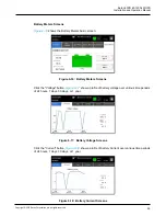
Page 107: ...ic screen Figure 6 16 Battery Meters Screens Click the Voltage button Figure 6 17 show a profile of battery voltage over various time periods of 24 hours 7 days 30 days or 1 year Figure 6 17 Battery Voltage Screens Click the Current button Figure 6 18 show a profile of battery Current over various time periods of 24 hours 7 days 30 days or 1 year Figure 6 18 Battery Current Screens ...

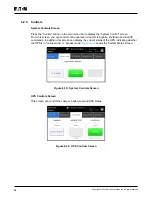
Page 108: ...ou can control online operation transfer to bypass shutdown and load off commands In addition this screen can display the current status of the UPS indicating whether the UPS is in online mode or bypass mode Figure 6 19 shows the System Status screen Figure 6 19 System Controls Screen UPS Controls Screen This screen can control the charger battery test and UPS status Figure 6 20 UPS Controls Scree...

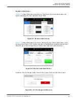
Page 109: ...ch UPM Figure 6 21 Module Controls Screen Figure 6 22 shows the Module Control screen By selecting any of the modules shown on the previous screen Figure 7 33 the user can observe full details of an individual module It also allows the user to move through various modules and modes while within this screen Figure 6 22 Module Control Detail Screen Select the Turn On Charger button there will be a p...

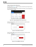
Page 110: ...tage Architecture operations are described in the UPS Installation and Operation manual for your system Figure 6 24 Energy Advantage Architecture EAA Screen Select the Enable ESS button there will be a pop up screen to confirm the request For details see Section 2 2 1 2 Figure 6 25 Enable ESS Confirmscreen Select the Enable VMMS button there will be a pop up screen to confirm the request For detai...

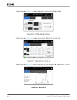
Page 111: ...onfirm the request For details see Section 2 3 1 Figure 6 27 Enable ABM Confirmscreen Select the Clear Alarms button there will be a pop up screen to confirm the request Figure 6 28 Clear Alarms Confirmscreen 6 2 6 Mimics Press the UPM Mimic on the main menu to display the mimic screen which is used to observe the power flow as shown in the figure below Figure 6 29 UPS Mimic Screen ...

Page 112: ...operator to control the individual UPMs Figure 6 30 UPS Module Map Screen The screen shown Figure 6 31 displays values for all UPS and UPM parameters Figure 6 31 System Overview Screen The screen shown Figure 6 32 allows the operator to visually obtain ESS mode efficiency values Figure 6 32 ESS Screen ...

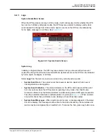
Page 113: ...s lights messages or all three Select Logs from the main menu screen to look at any currently active events System Event Horn The system event horn beeps to alert an operator that an event needing attention is taking place System Event Indicators The status indicators on the UPS control panel and the event horn let you know when the UPS system is operating in any mode other than Double Conversion ...

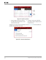
Page 114: ...number shown to the right of the box Each window shows four events The operator can also use the UP DOWN arrows above and below showing the number of events in the log Selecting an event opens the Event Detail screen shown in Figure 6 35 This screen details the specifics of the event for the user to see Figure 6 35 Active Event Detail Screen ...

Page 115: ...erved Service Log Screen The Service Log screen displays service alarms service notifications and service status as shown in the figure below Figure 6 36 Service Log Screen Change Log The Change Log screen displays the system configuration change information as shown in the figure below Figure 6 37 Change Log Screen ...

Page 116: ...onal statistics Figure 6 38 Statistics Data Detail Screen 6 2 9 Settings User Screen The screen shown in Figure 6 39 gives the operator access to basic system information such as serial number installed firmware version etc Touching the CLEAN SCREEN button disables the screen for 30 seconds to allow the user to safely clean the screen without affecting operation Figure 6 39 User Screen Screen ...

Page 117: ...ved Configuration Options Screen The screen shown in Figure 6 40 allows the operator to affect changes to various system values Figure 6 40 Configuration Options Screen Service Screen The Service screen is only used for Eaton service engineers as shown in the figure below Figure 6 41 Prompt for level 3 Password Screen ...

Page 118: ...ass Mode until the inverter turns on and the UPS transfers to Double Conversion Mode The status indicator on the UPS control panel indicates the UPS is in Bypass Mode If auto bypass is not enabled the UPS output remains off until the UPS system transfers to Double Conversion Mode 9 Observe the following messages appear sequentially on the System Controls screen STARTING ONLINE The rectifier and in...

Page 119: ...o Bypass Mode To transfer the critical load to Bypass Mode perform the following procedure NOTE In Bypass Mode the critical load is not protected from commercial power interruptions and abnormalities 1 Press the Controls button in the main menu The System controls screen appears 2 Press the Go to bypass button in the System Controls screen The UPS system transfers to Bypass Mode and the critical l...

Page 120: ...r System Mode to Double Conversion Mode Note that the Energy Saver System mode commands are displayed only if enabled at the factory or by an Eaton Customer Service Engineer To transfer the critical load to Double Conversion Mode 1 Switch to Setting service screen 2 Select EAA Controls 3 Select Disable ESS The UPS system transfers to Battery Mode and then to Double Conversion Mode If the power mod...

Page 121: ...emains off until restarted 1 Press Load Off The shut down screen appears providing a choice to proceed or abort the shutdown NOTE All power to the critical load is lost when Load Off is selected in the following step You should use this feature only when you want to de energize the critical load 2 To shut down the UPS press Load Off To abort the shutdown press ABORT When Load Off is selected the i...

Page 122: ... indicates the UPS is in Bypass Mode If auto bypass is not enabled the UPS output remains off until the UPS system transfers to Double Conversion Mode 9 Press the Go online button on the UPS control screen 10 Observe the following messages appear sequentially on the UPS status line STARTING ONLINE The rectifier and inverter turn on The DC voltage continues to ramp up to full voltage Once the DC li...

Page 123: ...des The UPM modules can be added reduced and changed online and the quantity of the N and X of the N X parallel redundancy system can be changed according to requirement at any time When the modules fail if only the quantity of the fault modules is less than or equal to X the fault UPM modules can be changed online without affecting the UPS running Options Supplied by the N X Parallel Redundancy S...

Page 124: ...he utility power has been input to the UPS unit To prevent safety accidents caused by dumping please install UPM in order from bottom to top UPM is too heavy and it is recommended to use a lifting platform for operation during installation WARNING The cover must be installed if the slot is not inserted in the UPM otherwise it will cause hot air to flow back 2 Remove the 4 screws on the cover and r...

Page 125: ...ront panel of the module to Two people each hold the handles located on the front panel of the UPS module with one of their hands and support the bottom of the module with the other hand respectively and they both use their strength together to draw the module outward smoothly and slowly until it is out and then support it together and put it on the ground or some other temporary supports gently 2...

Page 126: ...n press Module controls Select module screen is displayed 10 Select the UPM you want to start UPM 1 UPM X 11 The UPM control screen is displayed and the UPM status should indicate SHUTDOWN 12 On the UPM control screen select Start module 13 Verify the following messages display sequentially on the UPM status line READY ACTIVE The UPM rectifier and inverter turn on and the UPM will transfer to Doub...

Page 127: ...energize the critical load NOTE The following instructions are for the Eaton Corporation supplied EPO switch If a customersuppliedEPO switch is used it may not activate in the same manner refer to the operating instructions provided with the switch To use the EPO switch 1 Press the EPO pushbutton switch The input output and bypass backfeed relays open the battery breaker or disconnect is tripped a...

Page 128: ...itch Maintenance bypass switch MBS Figure 6 43 Double Conversion Mode 2 Perform transfer from double conversion mode to bypass mode as described in Section 6 3 3 Transfer from Double Conversion Mode to Bypass Mode Remember to verify the transfer before proceeding to the next step 3 Turn the MBS from UPS position to Bypass position 4 Perform the LOAD OFF procedure in Section 6 3 7 UPS System and Cr...

Page 129: ...Turn ON the rectifier switch to connect rectifier input to UPS 3 Turn ON the Static bypass switch toconnect UPS bypass input 4 Turn ON the output switch toconnect UPS Inverter output 5 Perform the UPS start up procedure bypass mode in Section 6 3 2 Starting the UPS System in Bypass Mode 6 Turn OFF the MBS and cut off the UPS maintenance bypass MBS output 7 Refer the Section 6 3 4 Transfer from Byp...

Page 130: ...or protective panels removed Do not make any assumptions about the electrical state of any cabinet in the UPS system Since each battery string is an energy source in itself opening the battery circuit breaker does not deenergize the voltage within the battery string DO NOT ATTEMPT TO ACCESS ANY INTERNAL AREA OF THE BATTERY STRING YOURSELF VOLTAGES ARE ALWAYS PRESENT IN THE BATTERY STRING If you su...

Page 131: ...nstallation Considerations and Chapter 8 TECHNICAL DATA 4 Ensure the UPS is in Normal Mode Normal status indicator is illuminated If an alarm lamp is illuminated or the Normal status indicator is not illuminated contact your service representative 7 2 2 MONTHLY Maintenance Perform the following steps monthly 1 Monitor system parameters on the control panel in Section 6 2 Steps to operate the UPS 2...

Page 132: ...rsonnel due to high energy and voltage Do not discard waste electrical or electronic equipment in the trash For proper disposal contact your local collecting recycling reuse or hazardous waste center and follow the local legislation These symbols indicate on a product Figure 7 1 WEEE Symbol Use proper local collecting centers meeting local legislation when handling waste of electrical and electron...

Page 133: ... change without notice 8 1 Standards Table 8 1 Standards Safety IEC 62040 1 IEC 60950 1 EMC Emissions IEC 62040 2 2005 EMC Immunity IEC 61000 2 2 Low frequency conducted IEC 61000 4 2 ESD IEC 61000 4 3 RF electromagnetic field IEC 61000 4 5 Surge IEC 61000 4 6 Conducted RF common mode IEC 61000 4 8 Power frequency magnetic field Performance Tests IEC 62040 3 2011 Environmental IEC 62430 RoHS 2002 ...

Page 134: ...ser configurable Frequency Tolerance 40 to 72 Hz Number of Input Phases Rectifier Input Number of Input Phases Bypass Input 3 phases N Optional Input Power Factor 0 99 Rated Mains Input Current Maximum Mains Input Current See Table 3 6 Rated and Maximum Currents for Rated Power and Voltage unit A Input Current Distortion at Rated Input Current iTHD 3 Rectifier Ramp up Rectifier Start and Load Step...

Page 135: ...e 0 1 Hz 1 Hz s Overload Capability at Ambien 30 C Ambient Temperature 10 min 125 load Overload Capability at Ambient 30 C Double Conversion Mode 60 min 102 110 load 10 min 111 125 30 sec 126 150 load 300 ms 150 load Overload Capability at Ambient 30 C on Inverter Stored Energy Mode 1 min 102 110 load 300 ms 110 load Overload Capability at Ambient 30 C on Bypass Continuous 115 load 10 ms 1000 load...

Page 136: ... Note Battery strings with different battery quantity and voltage may not be connected in parallel Battery Voltage 432V 36 blocks to 528V 44 blocks Recharge Profile ABM or float charge End of Discharge Voltage 1 67 VPC to 1 75 VPC configurable or automatic load adaptive Charge Current Configurable Single UPM default 4A configurable max 40A per UPM Battery Start Option Yes Note For external battery...

Page 137: ...m Service Altitude Maximum 2000m 6600ft with 1 derating per each additional 100m Relative Humidity Range 5 to 95 no condensation allowed Acoustic Noise at 1 m At 1m per ISO 7779 standard 300kW 74 6dB 600kW 78 8dB 1200kW 81 8 dB EMC IEC 62040 2 C3 Maximum recommended operating and storage temperature with VRLA batteries is 25 C Storage condition for UPS and spare parts store one year refer unit SN ...

Page 138: ...of the UPS shall also be performed only by a service engineer approved by Eaton Otherwise the warranty will be voided If the product fails to meet its published specifications due to a defect in material and workmanship covered by this warranty the seller will repair or replace the warranted product Such repair or replacement will be made by Eaton or by a service provider approved by Eaton Repair ...

Page 139: ...e been completed Optional The REPO device is mounted in its installed location and its wiring is terminated inside the UPS cabinet Optional A jumper wire is connected between pins 3 and 4 on the REPO terminal block if using a normally closed REPO switch Optional All terminal cover plates are installed Accessories are mounted in installed locations and wiring is terminated inside the UPS cabinet Op...

Page 140: ...en cabinets as required Ground conductors are properly installed CAN wiring between the UPSs is properly installed Pull chain wiring between the UPSs is properly installed Adequate workspace exists around the UPSs parallel tie cabinet and other cabinets Startup and operational checks are performed by an authorised Eaton Customer Service Engineer for parallel systems Battery wire has correctly pola...

Page 141: ...g Description Language Change the user interface language Unit Name Change the unit name Clock Change the date and time change the clock for mat or enable disable NTP clock setup Signal Inputs Select signal input name and function Relay Outputs Configure the relay outputs Battery Test Change the power level and duration for battery test Bypass Limits Change bypass voltage bypass frequency or by pa...

Page 142: ......

Page 143: ...614 40061 01 ...

Reviews: