background image

OPERATION

Eaton 9355-F47 Unirom UPS (10/15 kVA) User's Guide  

S

  164201642 Rev C

 www.eaton.com/powerquality

74

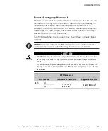
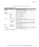
The following table shows the indicator status and description.

Indicator

Status

Description

Green

On

The UPS is operating normally.

Flashing

S

The UPS is starting up or is shut down and waiting for power to return.

S

A new information message is active.

S

Bypass is not available.

Off

The UPS is turned off and will not turn on automatically.

Yellow

On

The UPS is in Battery mode.

Yellow

On

The UPS is in Bypass mode.

Red

On

The UPS has an active alarm.

Flashing

There is a new UPS alarm condition. See “Troubleshooting” on page 101 for
additional information.

Changing the Language

Press and hold the first button on the left for approximately five seconds
to select the language menu. This action is possible from any LCD menu
screen.

Display Functions

As the default or after 15 minutes of inactivity, the LCD displays the
selectable startup screen. The default is the Eaton logo and can be
changed to the Mimic screen in the User Settings menu.

The backlit LCD automatically dims after a long period of inactivity. Press
any button to restore the screen.

Use the two middle buttons (  and  ) to scroll through the menu
structure. Press the 

 button to enter a submenu. Press the 

 button

to select an option. Press the 

ESC

 button to cancel or return to the

previous menu.

Summary of Contents for 9355-F47 Unirom

Page 1: ...Eaton 9355 F47 Unirom UPS 10 15 kVA User s Guide ...

Page 2: ...A Interference Causing Equipment meets all requirements of the Canadian Interference Causing Equipment Regulations ICES 003 Cet appareil numérique de la classe A respecte toutes les exigences du Reglement sur le matériel brouilleur du Canada IEC 62040 2 Some configurations are classified under IEC 62040 2 as C2 UPS for Unrestricted Sales Distribution Eaton ABM and X Slot are registered trademarks ...

Page 3: ...This symbol indicates that you should not discard the UPS or the UPS batteries in the trash This product contains sealed lead acid batteries and must be disposed of properly For more information contact your local recycling reuse or hazardous waste center This symbol indicates that you should not discard waste electrical or electronic equipment WEEE in the trash For proper disposal contact your lo...

Page 4: ......
Page 5: ...zards 10 Electrical Safety Features 11 Lockout Tagout Procedures 11 Personal Protective Equipment 11 Safety Labels 12 4 UPS Setup 15 Inspecting the Equipment 15 Floor Loading 16 Clearances 16 Unloading the UPS 17 5 UPS Installation 23 6 Stabilizing the UPS 31 7 Internal Battery Installation 33 Safety Warnings 33 Installing the Internal Batteries 36 8 Ultracapacitor Module Installation 45 Safety Wa...

Page 6: ...Initial Startup 78 UPS Startup 78 Unirom Setup and Operation 78 Setup Instructions 78 Unirom UPS PFU startup procedures 79 UPS PFU behavior with custom input output connection box for Unirom 79 UPS Shutdown 80 Emergency Machine Off 81 11 UPS Maintenance 83 UPS and Battery Care 83 Storing the UPS and Batteries or Ultracapacitor Module 83 When to Replace Batteries 84 Battery Type 84 Replacing the In...

Page 7: ...ations The Eaton 9355 F47 Unirom UPS continually monitors incoming electrical power and removes the surges spikes sags and other irregularities that are inherent in commercial utility power Working with a building s electrical system the UPS supplies clean consistent power that sensitive electronic equipment requires for reliable operation During brownouts blackouts and other power interruptions b...

Page 8: ...nitoring S Emergency shutdown control through the remote emergency power off REPO port and emergency machine off EMO switch S Permanent lockout feature on the input and output breakers S Start on battery capability for powering up the UPS even if utility power is not available only when battery trays are installed S Standard communication options with a DB 9 serial port relay output contacts and p...

Page 9: ...ture and humidity controlled indoor environment free of conductive contaminants Ambient temperature must not exceed 40 C 104 F Do not operate near water or excessive humidity 95 maximum S To reduce the risk of fire connect only to a circuit provided with 100 amperes maximum branch circuit overcurrent protection in accordance with the National Electrical Code NEC ANSI NFPA 70 S Output overcurrent p...

Page 10: ... installer l onduleur uniquement à l intérieur dans un lieu dépourvu de matériaux conducteurs où la température et l humidité ambiantes sont contrôlées La température ambiante ne doit pas dépasser 40 C Ne pas utiliser à proximité d eau ou dans une atmosphère excessivement humide 95 maximum S Afin de réduire les risques d incendie ne raccordez qu à un circuit muni d une protection de surintensité d...

Page 11: ...le este SIE en un lugar cubierto con temperatura y humedad controladas libre de contaminantes conductores La temperatura ambiente no debe exceder los 40 C No trabaje cerca del agua o con humedad excesiva 95 máximo S Para reducir el riesgo de incendio realice la conexión únicamente hacia un circuito que cuente con un máximo de 100 amperios de protección contra sobrecorriente de circuito derivado de...

Page 12: ...SAFETY WARNINGS Eaton 9355 F47 Unirom UPS 10 15 kVA User s Guide S 164201642 Rev C www eaton com powerquality 6 ...

Page 13: ...nstall the equipment at your site Safety Officer s Name Address Phone Home Work Pager Alternate Emergency Contact Medical Officer s Name Address Phone Home Work Pager Alternate Emergency Contact Personnel trained in emergency medical procedures Address Phone Home Work Pager Alternate Emergency Contact Nearest Fire Extinguishers Nearest Fire Exits Further emergency contact information Unirom Electr...

Page 14: ... 3 Operator engineer knows emergency contact information 4 Operator engineer is aware of all potential hazards 5 Operator engineer can identify all relevant warning labels 6 Operator engineer knows location of all EMO REPO buttons Hazards Summary Hazard alert labels and protective guards are used on potentially hazardous areas of the equipment These safeguards protect personnel from potential expo...

Page 15: ...set for AC voltage UPS input output terminal block inside the lower circuit breaker housing at the rear of the UPS Should read 0 volts Electric Shock Hazards Hazardous electrical voltages up to 208 Vac are present inside the equipment see Table 1 There is no threat to personnel safety if the equipment covers are in place and the safety features are not defeated The UPS includes batteries that shou...

Page 16: ...se severe injury or death Use a forklift or pallet jack to lift or move the UPS Have at least two people present when lifting or moving the UPS 35 2 894 mm 13 1 333 mm 6 0 153 mm 33 6 854 mm 13 1 333 mm 13 6 345 mm 7 0 180 mm 12 0 300 mm 32 2 818 mm 33 5 850 mm Weight 410 lb 186 kg 21 5 545 mm 2 0 50 8 mm EMO Pushbutton Stabilizing Bracket on rear of UPS Installed Conduit Figure 2 Installed UPS We...

Page 17: ...for personnel to follow while performing maintenance tasks Lockout Tagout Procedures Lockout tagout devices and procedures help prevent an accidental startup or a release of stored energy that could cause injury or equipment damage Follow all lockout tagout procedures included in the user s guide and any that are required at your site Modifying the equipment overriding or defeating the devices or ...

Page 18: ...5 F47 Unirom UPS 10 15 kVA User s Guide S 164201642 Rev C www eaton com powerquality 12 Safety Labels Figure 3 and Table 2 describe the safety and other labels on the UPS 11 12 3 2 1 4 5 6 7 9 10 8 Figure 3 UPS Label Locations ...

Page 19: ...WARNING Hazardous Voltage Enclosed 4 Hazard Alert WARNING Hazardous Voltage Enclosed 5 Hazard Alert WARNING Hazardous Voltage Enclosed 6 Hazard Alert WARNING High Leakage Current 7 Hazard Alert WARNING Hazardous Voltage Enclosed 8 Hazard Alert WARNING Hazardous Voltage Enclosed 9 Hazard Alert WARNING Hazardous Voltage Enclosed 10 Hazard Alert WARNING Hazardous Voltage Enclosed 11 Hazard Alert CAUT...

Page 20: ...SAFETY OVERVIEW Eaton 9355 F47 Unirom UPS 10 15 kVA User s Guide S 164201642 Rev C www eaton com powerquality 14 ...

Page 21: ...autions Inspecting the Equipment If any equipment has been damaged during shipment keep the shipping and packing materials for the carrier or place of purchase and file a claim for shipping damage If you discover damage after acceptance file a claim for concealed damage To file a claim for shipping damage or concealed damage 1 File with the carrier within 15 days of receipt of the equipment 2 Send...

Page 22: ...eling feet and casters Standard Model Floor Loadings Eaton 9355 F47 Unirom Maximum Weight without Batteries or Ultracapacitor Maximum Weight with Both Battery Trays or Ultracapacitor Point Loading lb in2 kg cm2 UPS 190 lb 86 2 kg 410 lb 186 kg 103 7 3 10 43 265 mm 8 15 207 mm 1 14 29 mm 9 31 236 5 mm 18 62 473 mm 22 28 566 mm 1 83 46 5 mm Leveling Feet 4x Casters 6x Figure 4 Leveling Feet and Cast...

Page 23: ... wooden pallet and protected with outer protective packaging material To unload the UPS 1 Carefully inspect the outer packaging for evidence of damage during transit 2 Use a forklift or pallet jack to move the packaged UPS to the installation site or as close as possible before unpacking Insert the forklift or pallet jack forks between the skids on the bottom of the pallet 3 Set the pallet on a fi...

Page 24: ...S 10 15 kVA User s Guide S 164201642 Rev C www eaton com powerquality 18 6 Remove the two M10 bolts securing the rear stabilizing bracket to the pallet see Figure 5 M10 Bolt M10 Bolt Figure 5 Removing the Rear Stabilizing Bracket Bolts ...

Page 25: ...o retain the rear stabilizing bracket and hardware for later re assembly onto the UPS NOTE Hold the UPS so that the bolts can be removed easily without the UPS rolling backward 8 Remove the two M10 bolts securing the front shipping bracket to the pallet Remove the four M4 screws securing the bracket to the cabinet front panel and remove the bracket See Figure 6 Rear Stabilizing Bracket M4 Screws u...

Page 26: ...ing crate onto the skids at the back of the pallet Verify that the flat side of the crate panel is facing up with the beveled edge pointing away from the pallet Secure the crate panel to the skids with two bolts See Figure 7 Figure 7 Unloading the UPS 10 Slowly roll the UPS toward the rear of the pallet If needed adjust the leveling feet so that the UPS will roll ...

Page 27: ...et to prevent tipping 11 With the UPS supported slowly roll the UPS down the ramp until the UPS is clear of the pallet and ramp see Figure 8 Figure 8 Clearing the Pallet and Ramp 12 Roll the UPS to the desired location 13 Continue to the following chapter UPS Installation NOTE If installation is delayed protect the unpacked UPS from moisture dust and other harmful contaminants Failure to store and...

Page 28: ...UPS SETUP Eaton 9355 F47 Unirom UPS 10 15 kVA User s Guide S 164201642 Rev C www eaton com powerquality 22 ...

Page 29: ...ian should perform the UPS installation and initial startup Risk of electrical shock To hardwire the UPS 1 Verify that the electrical connections to the installation site have been properly installed 2 A wall mounted user supplied readily accessible disconnection device must be incorporated in the input wiring Compare the circuit breaker ratings to the specifications in Table 3 on page 25 NOTE To ...

Page 30: ...t and output circuit breakers are in the OFF position see Figure 9 8 Using customer provided locks lock the input and output circuit breakers in the OFF position Display a DO NOT OPERATE tag completed with your name the date and the time of locking 9 Verify the absence of hazardous energy according to Table 1 on page 9 Conduit Knockouts Input and Output Circuit Breakers Battery Circuit Breaker Con...

Page 31: ...Function Feeder Circuit Breaker Rating L1 L2 L3 N Wire Size1 Tightening Torque L and N Ground Wire Size1 Tightening Torque Ground Conduit Size2 3 Number of Conduits 208 Input 60A 4 AWG 50 lb in 5 6 Nm 10 AWG 35 lb in 4 0 Nm 1 25 conduit 1 208 Output 60A 4 AWG 50 lb in 5 6 Nm 10 AWG 35 lb in 4 0 Nm 1 25 conduit 1 1 Use only 90 C rated copper wire Minimum wire size is based on 120 208 full load rati...

Page 32: ...f the wire barrel resting against the locator and the bottom of the terminal tongue facing the stationary die 5 Holding the wire in place activate the tool or power unit to complete the crimp 6 Inspect the crimped terminal to ensure the wire is fully inserted and flush with the end of the wire barrel and the crimp is centered on the wire barrel Do not use crimped terminals that do not meet these s...

Page 33: ...aton com powerquality 27 Figure 10 UPS Terminal Block 13 Optional Hard wire the remote EMO terminations for the UPS according to the following table Remote EMO Connections Wire Function Terminal Wire Size Rating Suggested Wire Size Remote EMO TB5 1 12 22 AWG 4 0 32 mm2 18 AWG 0 82 mm2 TB5 2 ...

Page 34: ...e 12 on page 29 for the complete UPS wiring diagram including the EMO circuit 1 2 EMO Circuit EMO Switch Internal EMO Switch External Customer Supplied TB5 Figure 11 Remote EMO Wiring Diagram For a detailed view of the EMO terminal block located on the UPS terminal block see Figure 10 14 Replace the UPS wiring access cover 15 Continue to Stabilizing the UPS on page 31 ...

Page 35: ...n com powerquality 29 9355 UPS L1 L2 L3 N L1 L2 L3 N CB2 Battery Module Batteries supplied by customer CB1 CB3 Shunt trip UV Trip EMO Circuit EMO Switch EMO Operation TB5 TB4 24V TB2 Input GFI K1 TB3 Output GFI K2 GFI Relay Input K1 GFI Relay Output K2 K1 NC K2 NC Figure 12 UPS Wiring Diagram ...

Page 36: ...UPS INSTALLATION Eaton 9355 F47 Unirom UPS 10 15 kVA User s Guide S 164201642 Rev C www eaton com powerquality 30 ...

Page 37: ...bolts and hardware with 1 3125 33 34 mm minimum embedment for 3000PSI strength concrete Refer to your local building codes for seismic requirements See Figure 15 for the floor bolt pattern To stabilize the UPS 1 Lower the leveling feet to prevent the UPS from rolling Figure 13 Lowering the Leveling Feet 2 Attach the stabilizing bracket to the bottom of the UPS rear panel using the retained hardwar...

Page 38: ...n com powerquality 32 M4 Screws Figure 14 Stabilizing Bracket Installation 2 06 52 50 mm 3 65 92 85 mm 5 51 139 90 mm 15 95 405 10 mm 17 80 452 15 mm 19 39 492 50 mm 0 125 3 18 mm 0 56 14 30 mm 4X 0 56 14 30 mm 2X Slot 3 06 77 70 mm X 1 30 33 15 mm Figure 15 Stabilizing Bracket Floor Bolt Pattern ...

Page 39: ...sulated handles 3 Do not lay tools or metal parts on top of batteries 4 Disconnect charging source prior to connecting or disconnecting battery terminals 5 Wear rubber gloves and boots S When replacing batteries replace with the same type and number of batteries or battery packs Contact your service representative to order new batteries S Proper disposal of batteries is required Refer to your loca...

Page 40: ...es isolantes 3 Ne déposez pas d outils ou de pièces métalliques sur les batteries 4 Déconnectez la source de chargement avant de connecter ou de déconnecter les bornes de batterie 5 Portez des gants et des bottes en caoutchouc S Remplacez uniquement les batteries par des batteries ou blocs de batteries présentant les mêmes type et numéro S Une mise au rebut réglementaire des batteries est obligato...

Page 41: ...con manijas aisladas 3 No coloque herramientas o piezas de metal en la parte superior de las baterías 4 Desconecte la fuente de carga antes de conectar o desconectar las terminales de la batería 5 Utilice guantes y botas de hule S Cuando se reemplacen las baterías cámbielas con el mismo tipo y número de baterías o paquetes de baterías S Es necesario desechar las baterías de un modo adecuado Consul...

Page 42: ...will be present when performing the steps in this section To install the internal batteries 1 Verify that the input output and battery circuit breakers are in the OFF position see Figure 16 2 Verify that the input and output battery circuit breakers have appropriate lockout tagout devices installed UPS Battery Circuit Breaker Input and Output Circuit Breakers Figure 16 UPS Rear View ...

Page 43: ...15 kVA User s Guide S 164201642 Rev C www eaton com powerquality 37 3 Remove the UPS lower front cover Press and release the handle latch at the bottom of the cover and then lift the cover up and off the cabinet see Figure 17 Figure 17 Removing the Front Cover ...

Page 44: ...powerquality 38 4 The battery cover panel is made up of two parts joined together with four screws Remove both parts of the panel at the same time by removing the 10 M4 screws on the edges of the panel and the M4 screw in the middle of the panel see Figure 18 M4 Screws Figure 18 Removing the Battery Cover Panel ...

Page 45: ... performance is not affected 7 For the first tray set the battery tray on an adjustable height table customer provided Adjust the table so its height is at a comfortable working level 8 Install 12 vinyl caps on the battery tray dividers as shown in Figure 19 9 Insert eight batteries into the battery tray see Figure 20 10 Connect the batteries in the tray as shown in Figure 19 and Figure 20 11 Secu...

Page 46: ...40 Figure 20 Battery Tray with Batteries 12 Adjust the height of the adjustable table to be level with the top tray location in the UPS 13 Load the battery tray into the top tray location in the UPS 14 Repeat Steps 7 through 13 for the second battery tray Load the second battery tray into the bottom tray location in the UPS ...

Page 47: ...0 15 kVA User s Guide S 164201642 Rev C www eaton com powerquality 41 15 Connect the two battery trays together by connecting the black connector from the top tray to the red connector from the bottom tray See Figure 21 Figure 21 Connecting the Battery Trays ...

Page 48: ... to the battery terminals as described below see Figure 22 Connect the red connector from the electronics module to the red connector from the top tray Route the remaining electronics module wire with the black connector through the bushing to the bottom shelf Connect the black connector from the electronics module to the black connector from the bottom tray Figure 22 Connecting the Battery Circui...

Page 49: ...quality 43 17 Reinstall the battery cover panel 18 Replace the UPS lower front cover 19 Continue to one of the following sections S Communication on page 55 to install UPS communication options such as X Slot cards S Operation on page 73 to start up the UPS Remove the lockout tagout devices before starting up the UPS ...

Page 50: ...INTERNAL BATTERY INSTALLATION Eaton 9355 F47 Unirom UPS 10 15 kVA User s Guide S 164201642 Rev C www eaton com powerquality 44 ...

Page 51: ...ns that require only short 1 to 3 second backup times The module consists of multiple ultracapacitors in a single enclosure with connections that plug into the existing battery connectors The module is internally fused to provide additional protection Attach Red Connector to Red Connector on Electronics Module Attach Black Connector from Electronics Module Figure 23 Ultracapacitor Module ...

Page 52: ...service personnel knowledgeable of ultracapacitor modules and required precautions Keep unauthorized personnel away from ultracapacitor module contacts S When replacing an ultracapacitor module replace with the same type Contact your service representative to order a new ultracapacitor module S Proper disposal of the ultracapacitor module is required Refer to your local codes for disposal requirem...

Page 53: ...isé par du personnel qualifié connaissant bien l ultracondensateur et les précautions nécessaires N autorisez aucun personnel non qualifié à manipuler l ultracondensateur S Remplacez uniquement l ultracondensateur par un ultracondensateur présentant les mêmes type Contactez votre service après vente pour commander un nouveau ultracondensateur S Une mise au rebut réglementaire de l ultracondensateu...

Page 54: ... de alta capacidad y esté al tanto de las precauciones requeridas debe darle servicio al equipo Mantenga al personal no autorizado alejado del condensador de alta capacidad S Cuando se reemplace el condensador de alta capacidad cámbielas con el mismo tipo de condensador de alta capacidad Contacte con su representante para pedir el condensador de alta capacidad nuevo S Es necesario desechar el cond...

Page 55: ...e will be present when performing the steps in this section To install the internal ultracapacitor module 1 Verify that the input output and battery circuit breakers are in the OFF position see Figure 24 2 Verify that the input and output battery circuit breakers have appropriate lockout tagout devices installed UPS Battery Circuit Breaker Input and Output Circuit Breakers Figure 24 UPS Rear View ...

Page 56: ...10 15 kVA User s Guide S 164201642 Rev C www eaton com powerquality 50 3 Remove the UPS lower front cover Press and release the handle latch at the bottom of the cover and then lift the cover up and off the cabinet see Figure 25 Figure 25 Removing the Front Cover ...

Page 57: ...rquality 51 4 The internal cover panel is made up of two parts joined together with four screws Remove both parts of the panel at the same time by removing the 10 M4 screws around the edges of the panel and the single M4 screw in the middle of the panel see Figure 26 M4 Screws Figure 26 Removing the Internal Cover Panel ...

Page 58: ...nit is firmly seated against the stops at the rear of the cabinet Verify that the holes on the mounting frame line up with the holes in the cabinet rails 6 Secure the ultracapacitor module to the frame using 2 screws and washers See Figure 27 Red Connector Black Connector Hold Down Screw and Washer Hold Down Screw and Washer Upper Shelf with Bushing Figure 27 Ultracapacitor Module Installed in Cab...

Page 59: ...ed connector to the red connector on the ultracapacitor module cable Route the remaining cable with the black connector through the bushing to the bottom shelf Connect the black connector from the electronics module to the internal socket connector on the ultracapacitor module 8 Reinstall the internal cover panel 9 Replace the UPS lower front cover 10 Continue to one of the following sections S Co...

Page 60: ...ULTRACAPACITOR MODULE INSTALLATION Eaton 9355 F47 Unirom UPS 10 15 kVA User s Guide S 164201642 Rev C www eaton com powerquality 54 ...

Page 61: ...wer management software S Remote emergency power off REPO S Relay output contacts S Programmable signal inputs Figure 28 shows the location of the communication options and control terminals on the UPS 1 2 1 2 1 2 1 2 1 2 3 DB 9 Communication Port REPO normally closed REPO normally open Signal Input 2 Signal Input 1 X Slot Communication Bay 2 X Slot Communication Bay 1 Relay Output Contacts Figure...

Page 62: ...he communication options and control terminals 1 Remove the front covers of all cabinets starting with the top cabinet Press and release the handle latch at the bottom of each cover and then lift the cover up and off the cabinet see Figure 29 Figure 29 Removing the Front Covers 2 Install the appropriate X Slot card and or necessary cable s into the top cabinet see Figure 28 and Figure 30 ...

Page 63: ...ww eaton com powerquality 57 Figure 30 Installing Communication Cables 3 On the bottom cover remove a knockout tab in the top edge of the cover for each cable With wire cutters cut either side of the tab and twist down to remove the tab see Figure 31 Figure 31 Removing Knockout Tabs ...

Page 64: ...mmunication Options or Control Terminals on page 68 for detailed information 6 Reinstall the front covers starting with the bottom cabinet see Figure 32 Hang the top edge of the cover on the cabinet first then lower the bottom edge and snap into place Be sure the cables fit in the access holes in the covers Figure 32 Reinstalling the Front Covers 7 Continue to Operation on page 73 to start up the ...

Page 65: ...DB 9 Communication Port Any X Slot card Any X Slot card Not in use Any X Slot card Eaton Relay Interface Card Available Any X Slot card Not in use Available NOTE You can configure relays signal inputs and the serial port baud rate through the front panel menus see Table 10 on page 76 DB 9 Communication Port To establish communication between the UPS and a computer connect your computer to the UPS ...

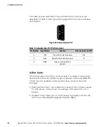
Page 66: ...rom the UPS 2 TxD Transmit to external device Out 3 RxD Receive from external device In 5 GND Signal common tied to chassis X Slot Cards X Slot cards allow the UPS to communicate in a variety of networking environments and with different types of devices The Eaton 9355 F47 Unirom has two available communication bays for any X Slot card including S Relay Interface Card has isolated dry contact Form...

Page 67: ...as monitoring through a Web browser interface connects to a twisted pair Ethernet 10 100BaseT network It is compatible with Eaton IPM IPP software Power Xpert monitoring software and also provides ModBus TCP connectivity to allow setup of UPS shutdown schedules as well as UPS test and control In addition you can attach an Environmental Monitoring Probe to obtain humidity temperature smoke alarm an...

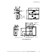
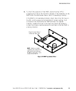
Page 68: ...n of the UPS from virtually any location within your facility up to 152 4m 500 ft from the UPS You can surface mount an RMP on a desktop or on a wall wherever you have a serial interface line Figure 35 shows an RMP Figure 36 shows the enclosure dimensions and cable exit openings Horn Silence Button Cable Exit Opening for 1 2 Conduit or Provided Strain Relief Figure 35 Remote Monitor Panel ...

Page 69: ...S 164201642 Rev C www eaton com powerquality 63 Mounting Slots 6 places NOTE Matches mounting holes on a single or double gang electrical box Cable Exit Openings for 1 2 Conduit or Provided Strain Relief 3 places Dimensions are in mm inches Figure 36 RMP Dimensions ...

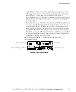
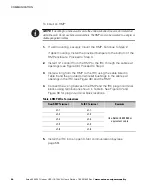
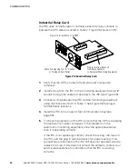
Page 70: ... 2 Install 1 2 conduit from the RMP to the IRC through the cable exit openings see Figure 36 Proceed to Step 4 3 Install wiring from the RMP to the IRC using the cable listed in Table 6 and the provided strain relief bushings in the cable exit openings in the IRC see Figure 38 and the RMP 4 Connect the wiring between the RMP and the IRC plug in terminal blocks using terminations shown in Table 6 S...

Page 71: ...ing correctly check the wiring the fuse on the IRC and the plug in terminal blocks for proper seating If all connections are secure but the RMP still does not operate correctly replace the fuse If this does not correct the problem contact your service representative for verification that the RMP is working correctly Plug in Terminal Block J1 to Industrial Relay Card NOTE Conduit and wiring supplie...

Page 72: ... the cable exit opening in the IRC see Figure 38 3 Connect wiring between the IRC and the monitoring equipment using terminations shown in Table 7 See Figure 38 for plug in terminal block locations 4 Install the IRC into an open X Slot communication bay see page 56 5 To check the operation of the IRC ensure that the UPS is supplying the load via the inverter or bypass If the indicators on the cust...

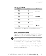
Page 73: ...er management software and an interface cable To begin installing power management software see the instructions accompanying the Software Suite CD NOTE Use only the supplied communication cable to connect the UPS to your computer Power management software provides up to date graphics of UPS power and system data and power flow It also gives you a complete record of critical power events and it no...

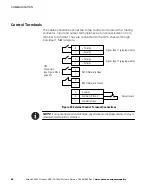
Page 74: ...They are connected to the UPS chassis through individual 1 MΩ resistors Polarity Polarity 2 1 Polarity Polarity 2 1 2 1 2 1 Signal Input 1 programmable Signal Input 2 programmable REPO Normally Open REPO Normally Closed Normally Open Normally Closed 1 2 Common 3 Relay Output UPS Connectors see Figure 28 on page 55 Figure 39 External Control Terminal Connections NOTE If using a semiconductor switch...

Page 75: ...itches may be used they should have normally closed contacts NOTE To restart the UPS reset the REPO switches and turn on the UPS manually The switches must be closed to keep the UPS running Maximum resistance is 10 ohm CAUTION S The REPO must not be connected to any utility connected circuits Reinforced insulation to the utility is required The REPO switch must have a minimum rating of 24 Vdc and ...

Page 76: ...o any utility connected circuits Reinforced insulation to the utility is required The relay output contacts must have a maximum rating of 30 Vac 1A and 60 Vdc 2A nominal values Programmable Signal Inputs The UPS incorporates two programmable signal inputs see Figure 28 on page 55 Use of non polar relay control input is recommended The pins must be shorted with maximum resistance of 10 ohm in order...

Page 77: ...e the UPS transfers to inverter operation if not prohibited by REPO or an alarm condition Force Bypass If active the UPS is forced to static bypass operation regardless of the bypass status External Battery Breaker Status If active the UPS knows that the batteries are disconnected Building Alarm 1 6 These alarms can be activated separately or at the same time with other building alarms Not in Use ...

Page 78: ...COMMUNICATION Eaton 9355 F47 Unirom UPS 10 15 kVA User s Guide S 164201642 Rev C www eaton com powerquality 72 ...

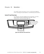
Page 79: ...l operation and UPS startup and shutdown Control Panel Functions The UPS has a four button graphical LCD with backlight It provides useful information about the UPS itself load status events measurements and settings see Figure 40 Power On Indicator green On Battery Indicator yellow Bypass Indicator yellow Alarm Indicator red Control Buttons for the LCD Menu Options Figure 40 Eaton 9355 F47 Unirom...

Page 80: ...ew UPS alarm condition See Troubleshooting on page 101 for additional information Changing the Language Press and hold the first button on the left for approximately five seconds to select the language menu This action is possible from any LCD menu screen Display Functions As the default or after 15 minutes of inactivity the LCD displays the selectable startup screen The default is the Eaton logo ...

Page 81: ...ntime Input L N and L L Current Frequency Bypass L N and L L Frequency Control Go to Bypass Mode Transfers the UPS to internal Bypass mode When this command is active the option changes to Go to Normal Mode Start Battery Test Initiates a battery test Display Test Four different selectable tests for the front panel functions the LEDs cycle through the alarm beep sounds the backlight turns off and o...

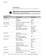
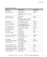
Page 82: ...Language English Elegir idioma Español English Relay Config Relay Alarm 1 X Slot 1 1 2 3 4 or X Slot 2 1 2 3 4 Setup Battery Low On Battery On Bypass UPS ok custom empty Alarm 1 empty X Slots 1 or 2 1 UPS ok 2 On Bypass 3 Summary Alarm 4 On Battery Signal Inputs empty Logic see Programmable Signal Inputs on page 70 empty Serial Port Config Port X Slot 1 X Slot 2 Serv Speed 19200 9600 2400 1200 192...

Page 83: ...option is not used 120V 208V Bypass Voltage High Limit 1 through 20 1 increments 120V 10 Bypass Voltage Low Limit 1 through 20 1 increments 120V 15 Nominal Output Frequency 50 Hz or 60 Hz 60 Hz Synchronization Enabled Disabled Enabled Synchronization Window 0 5 through 3 0 Hz 0 1 Hz increments 2 0 Hz Unsynchronized Transfer to Bypass Allowed Not Allowed Not Allowed Output Frequency Slew Rate 0 1 t...

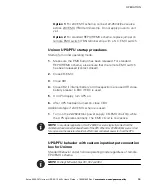
Page 84: ...r the UPS Contact service in advance usually a two week notice is required to reserve a preferred startup date UPS Startup WARNING Only qualified service personnel such as a licensed electrician should perform the UPS installation and initial startup Risk of electrical shock Verify that UPS installation has been carried out correctly and the UPS ground has been connected Unirom Setup and Operation...

Page 85: ... Close CB2 if internal battery or Ultracapacitors are used OR close battery breaker in EBC if EBC is used 5 On UPS display turn UPS on 6 After UPS has been turned on close CB3 Additional steps if 24V EMO scheme is used 1 Turn on the 22 26Vdc Vac power supply CB EMO shall trip while the UPS operates normally The EMO circuit is now active NOTE In a customer application this 22 26Vdc Vac source typic...

Page 86: ...s used opening CB EMO shall trip CB1 CB2 and CB3 If 24 V EMO scheme is used removing the 22 26Vdc Vac source across 24V EMO TB4 terminal strip shall trip CB1 CB2 and CB3 If standard REPO REMO scheme is used activating remote EPO EMO switch shall trip CB1 CB2 and CB3 UPS Shutdown To shut down the UPS 1 Press any button on the front panel display to activate the menu options 2 Press the button on th...

Page 87: ...81 6 Switch off utility power where the UPS is connected Emergency Machine Off To use the emergency machine off EMO switch 1 Press the large red EMO switch on top of the UPS The UPS immediately stops supplying power to the load The UPS disconnects from the batteries and opens the input and output breakers ...

Page 88: ...OPERATION Eaton 9355 F47 Unirom UPS 10 15 kVA User s Guide S 164201642 Rev C www eaton com powerquality 82 ...

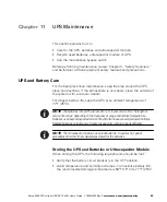
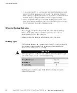
Page 89: ...y life keep the UPS at an ambient temperature of 77 F 25 C NOTE The batteries in the UPS are rated for a 3 5 year service life The length of service life varies depending on the frequency of usage and ambient temperature Batteries used beyond expected service life will often have severely reduced runtimes Replace batteries at least every 5 years to keep units running at peak efficiency NOTE The ul...

Page 90: ...ive When to Replace Batteries When the indicator flashes and the LCD panel displays Battery Failure the batteries may need replacing Contact your service representative to order new batteries Replace change the batteries approximately every five years Battery Type The following battery type is supplied with the UPS Only the following type is recommended Use of any other battery type inside Eaton c...

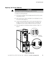
Page 91: ...mmediate area that the UPS is under maintenance control 2 Verify that the input output and battery circuit breakers are in the OFF position see Figure 41 3 Using customer provided locks lock the input and output circuit breakers in the OFF position Display a DO NOT OPERATE tag completed with your name the date and the time of locking 4 Verify the absence of hazardous energy according to Table 1 on...

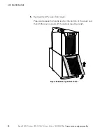
Page 92: ...User s Guide S 164201642 Rev C www eaton com powerquality 86 5 Remove the UPS lower front cover Press and release the handle latch at the bottom of the cover and then lift the cover up and off the cabinet see Figure 42 Figure 42 Removing the Front Cover ...

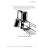
Page 93: ...ality 87 6 The battery cover panel is made up of two parts joined together with four screws Remove both parts of the panel at the same time by removing the 10 M4 screws on the edges of the panel and the M4 screw in the middle of the panel see Figure 43 M4 Screws Figure 43 Removing the Battery Cover Panel ...

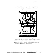
Page 94: ... the electronics module to the battery terminals as described below see Figure 44 Disconnect the red connector from the electronics module from the red connector from the top tray Disconnect the black connector from the electronics module from the black connector from the bottom tray Figure 44 Disconnecting the Battery Circuit Breaker Wires ...

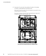
Page 95: ...onnector from the top tray from the red connector from the bottom tray See Figure 45 Figure 45 Disconnecting the Battery Trays 9 Place an adjustable height table customer provided near the UPS Adjust the table so its height is level with the top battery tray 10 Place the spike of a T bar handle through one of the holes on the top battery tray lip Pull the tray onto the table ...

Page 96: ...e batteries to be installed are the type listed in Battery Type on page 84 Use batteries of the same age type and manufacturer so that UPS performance is not affected 14 Verify that 12 vinyl caps are installed on the battery tray dividers as shown in Figure 46 15 Insert eight batteries into the battery tray see Figure 47 16 Connect the batteries in the tray as shown in Figure 46 and Figure 47 17 S...

Page 97: ...42 Rev C www eaton com powerquality 91 Figure 47 Battery Tray with Batteries 18 Load the battery tray into the top tray location in the UPS 19 Repeat Steps 9 through 18 for the second battery tray Remove and load the second battery tray at the bottom tray location in the UPS ...

Page 98: ...A User s Guide S 164201642 Rev C www eaton com powerquality 92 20 Connect the two battery trays together by connecting the black connector from the top tray to the red connector from the bottom tray See Figure 48 Figure 48 Connecting the Battery Trays ...

Page 99: ... from the electronics module to the battery terminals as described below see Figure 49 Connect the red connector from the electronics module to the red connector from the top tray Connect the black connector from the electronics module to the black connector from the bottom tray Figure 49 Connecting the Battery Circuit Breaker Wires ...

Page 100: ... They may explode Proper disposal of batteries and ultracapacitor modules is required Refer to your local codes for disposal requirements S Do not open or mutilate the batteries or ultracapacitor module Released electrolyte is harmful to the skin and eyes It may be toxic CAUTION Do not discard the UPS or the UPS batteries or ultracapacitor module in the trash This product contains sealed lead acid...

Page 101: ...ions and weights S Environmental and safety specifications S Technical specifications S Model specifications S Battery specifications S Battery runtimes Table 11 Model List UPS Description Power Rating 9355 F47 Unirom UPS with one battery section or ultracapacitor module 10 kVA 9 kW 15 kVA 13 5 kW Table 12 Dimensions and Weights Dimensions H W D Weight UPS 36 7 12 33 5 93 30 85 cm 410 lb 186 kg ...

Page 102: ...attery storage 59 F to 77 F 15 C to 25 C Ventilation Front air intake forced air two fans positive pressurization temperature UPS monitored Altitude 9 843 ft 3 000m operating without derating 32 810 ft 10 000m during transportation Relative Humidity 5 95 noncondensing Audible Noise 56 dBA at 1 meter distance typical loads 62 dBA for heavy load high ambient or high altitude on battery Surge Suppres...

Page 103: ...minal line conditions Input Rated Voltage 120 208 Vac three phase Input Frequency Range 45 65 Hz Input Rated Frequency 50 60 Hz selectable auto configuring Output Voltage Regulation 1 static Phase to Neutral 2 static Phase to Phase 5 dynamic at 100 resistive load change Response time 1 ms Output Voltage Distortion 2 THD linear load 5 THD non linear load Output Frequency 50 60 Hz selectable or auto...

Page 104: ...attery Specifications Battery Type 17 Ah sealed valve regulated lead acid VRLA maintenance free minimum 3 year float service life at 25 C 77 F voltage 192 Vdc 96 cells per string Number of Strings 1 string Battery Replacement Must be replaced by a qualified service technician Charger Service configurable 0 5 34A per string with overall maximum of 34A limited by input current Default 3 4A per strin...

Page 105: ...e black manufactured by Protech Chemicals Ltd Reference color spec HBT100730 MPN HX512N304 NOTE To review the latest version of each visit www 3Eonline com Enter username eatgenraleigh and password raleigh Use material names as search terms Suppliers periodically update their MSDS information visit the website frequently Verify that the MSDS you read is issued by the manufacturer and not by a thir...

Page 106: ...SPECIFICATIONS Eaton 9355 F47 Unirom UPS 10 15 kVA User s Guide S 164201642 Rev C www eaton com powerquality 100 ...

Page 107: ...ntrol panel for a list of active alarms If an alarm appears with a service code please contact the Help Desk see page 103 Alarm or Condition Possible Cause Action On Battery LED is on 1 beep every second A utility failure has occurred and the UPS is in Battery mode The UPS is powering the equipment with battery power Prepare your equipment for shutdown Battery Low LED is on Continuous beep for 10 ...

Page 108: ... breaker is on The remote emergency power off REPO switch is active or the REPO connector is missing Reset the REPO switch and restart the UPS Verify that the REPO connector is present Power is not available at the UPS output receptacles The UPS is in Standby mode Supply power to the connected equipment Press any button on the front panel display to activate the menu options Press the button on th...

Page 109: ...following telephone numbers and ask for a UPS technical representative United States 1 800 843 9433 or 1 919 870 3028 Canada 1 800 461 9166 ext 260 All other countries Call your local service representative Please have the following information ready when you call for service S Model number S Serial number S Firmware version number S Date of failure or problem S Symptoms of failure or problem S Cu...

Page 110: ...TROUBLESHOOTING Eaton 9355 F47 Unirom UPS 10 15 kVA User s Guide S 164201642 Rev C www eaton com powerquality 104 ...

Page 111: ...ace such defective Warranted Item not including the costs of labor coverage The defective Warranted Item will be refurbished or replaced onsite at the End User s location or such other location as determined by Eaton Any parts that are replaced may be new or reconditioned All parts replaced by Eaton shall become the property of Eaton LIMITED WARRANTY PERIOD The period covered by this Warranty for ...

Page 112: ...LIGATIONS In order to receive the benefits of this Warranty the End User must register the product warranty via mail or online at www eaton com PQ Register use the Product in a normal way follow the Product s user s guide and protect against further damage to the Product if there is a covered defect OTHER LIMITATIONS Eaton s obligations under this Warranty are expressly conditioned upon receipt by...

Reviews: